Form RZ-NA-I-LDAP, P/N 207733 (Rev 2), Page 16
Multiple Heater
Control - Option
CL31 and Option
CL32
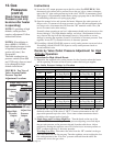
If the heater was ordered with a multiple heater control option, one thermostat can be used
to control multiple heaters. The option will control a maximum of six Size 400 heaters, a
maximum of three Size 800 heaters, or a maximum of two Size 1200 heaters.
The option includes a 40 VA transformer that replaces the standard transformer in the
”master” heater and a relay assembly that attaches to the “slave” heater. Option CL31
provides for control of two heaters. If control of additional heaters is desired, Option CL32
which is the relay assembly only must be added to each of the “slave” heaters.
The option packages are shipped separately and include complete instructions for installa-
tion and wiring.
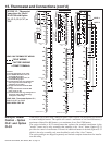
W2
R
W1
G
W
(OPT CL1) W.R. 1C30-341 THERMOSTAT
R
R
(OPT CL2) W.R. 1C30-341
W-S23-6 SUBBASE
W
G
W2
R
W1
G
Q674G SUBBASE
(OPT CL7) T874F THERMOSTAT
W2
R
W1
Q674C SUBBASE
(OPT CL18) T874F THERMOSTAT
RH
W2
RC
W1
G
W2
W1
R
G
(OPT CL3) T874F THERMOSTAT OR
R
W2
W1
G
W2
W1
R
G
W2
R
G
W1
NOTE 3
R
PR
PR
R
PR
R
PR
R
PR
R
PR
R
Y2
Y1
C
UNIT #1
TERMINAL STRIP
Y2
Y1
C
UNIT #1
TERMINAL STRIP
Y2
Y1
C
TERMINAL STRIP
UNIT #2
Y2
Y1
C
TERMINAL STRIP
UNIT #2
Y2
Y1
C
Y2
Y1
C
TERMINAL STRIP
UNIT #3
UNIT #3
TERMINAL STRIP
TERMINAL STRIP
Q674G SUBBASE
(OPT CL7) T874F THERMOSTAT
R
W2
Q674C SUBBASE
(OPT CL18) T874F THERMOSTAT
W1
RH
RC
G
W2
W1
Y1
Y2
C
W2
R
W1
G
SINGLE STAGE HEATING
SINGLE STAGE HEATING
WITH RECIRCULATION
TWO STAGE HEATING
UNIT #1
R
PR
W2
C
R
R
W1
G
PR
W2
Y2
Y1
C
R
W1
R
G
PR
TERMINAL STRIP
UNIT #2
Y2
Y1
TERMINAL STRIP
UNIT #3
FACTORY WIRING
CRIMP TERMINAL
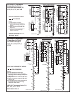
LDAP 1200 THERMOSTAT WIRING
FIELD WIRING
WD# 189506 REV. #2
LDAP 1200 - Thermostat Option CL1,
CL2, CL3, CL7 or CL18
NOTES:
1) Set the anticipator at 0.6 amps.
2) For 400,000 BTUH low fire, do
not install this jumper.
3) For 800,000 BTUH low fire, do
not install this jumper.
4) Set thermostat first stage anticipator
at 0.6 amps and and second stage
anticipator at 0.2 amps.
5) Jumper thermostat terminals RH
to RC.
6) Jumper thermostat terminals RH
to RC and G to W1.
7) Set thermostat first stage anticipator at
maximum amps and second stage
anticipator at 0.6 amps.
(SEE NOTE #1)
CL2
CL1
CL3
(SEE NOTE #7)
CL18
CL7
(SEE NOTES #6 & #7)
(SEE NOTE #1)
CL18
CL7
(SEE NOTE #4 AND #5)
(SEE NOTE #4)
NOTE 2
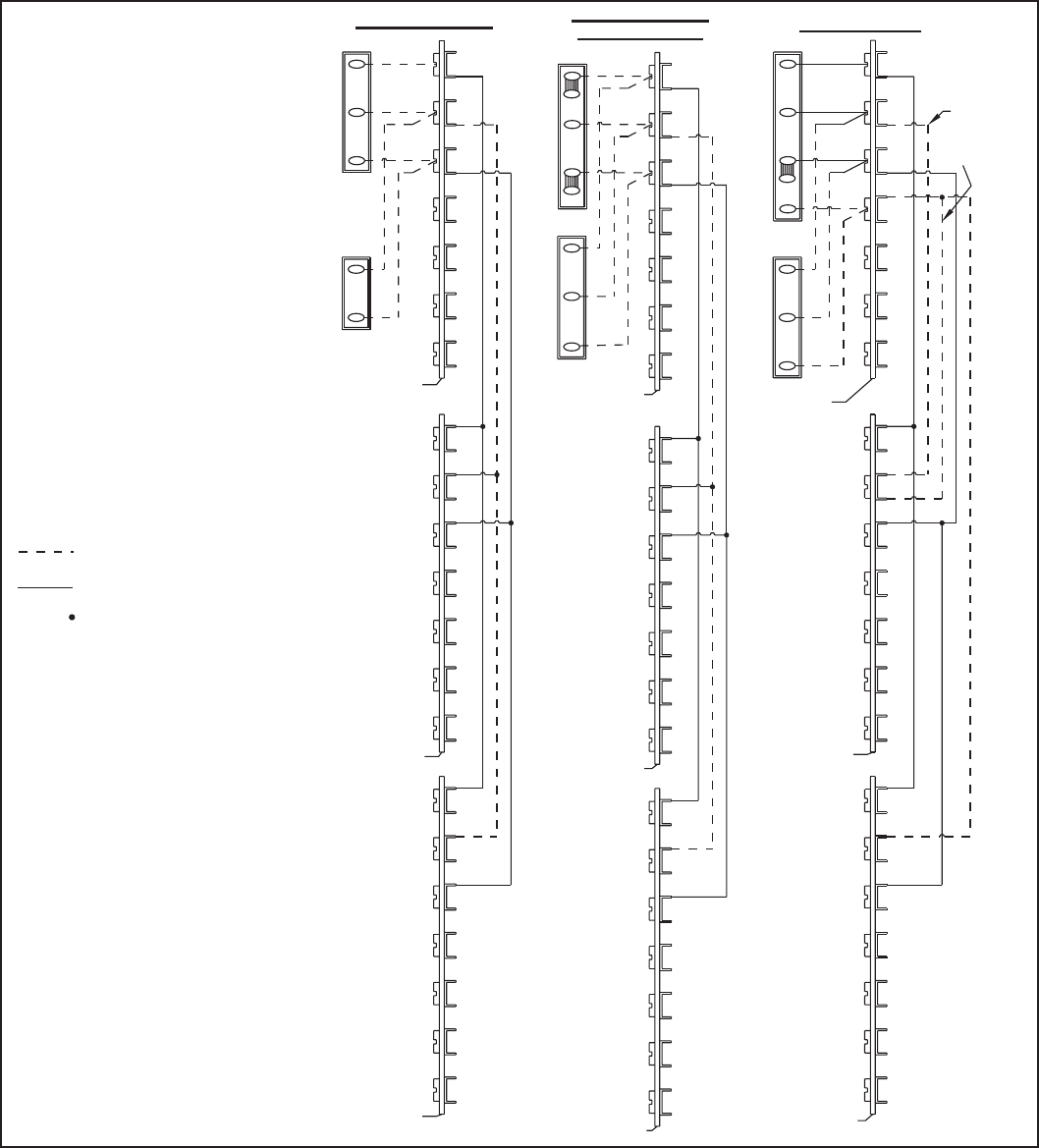
FIGURE 12 - Thermostat
Connections for Model
LDAP 1200 with Option
CL1, CL2, CL3, CL7, or
CL18
15. Thermostat and Connections (cont’d)


