


Form RZ-NA-I-LDAP, P/N 207733 (Rev 2), Page 28
7) Vent Terminal
(Pipe and Vent
Cap)
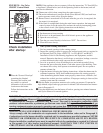
Horizontal Vent Terminal Clearances
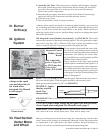
A vent cap is required. Maintain a minimum
clearance of 12 inches (305mm) from the wall
to the vent terminal cap for stability under
wind conditions.
Products of combustion can cause discolora-
tion of some building finishes and deteriora-
tion of masonry materials. Applying a clear
silicone sealant that is normally used to pro-
tect concrete driveways can protect masonry
materials. If discoloration is an esthetic prob-
lem, relocate the vent or install a vertical vent.
Support horizontal vent runs every six feet (1.8M). Support vertical runs of Type
“B” double-wall or Category III vent pipe in accordance with the requirements of
the pipe manufacturer. Support single-wall pipe in accordance with accepted indus-
try practices. Do not rely on the heater for support of either horizontal or vertical
vent pipe. Use non-combustible supports on vent pipe.
5) Vent System
Support
6) Condensation
Any length of single-wall vent pipe exposed to cold air or run through an unheated
area or an area with an ambient temperature of 45°F or less must be insulated along
its entire length with a minimum of 1/2" foil-faced fiberglass, 1-1/2# density insu-
lation. Where extreme conditions are anticipated, install a means of condensate
disposal.
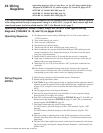
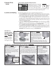
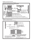
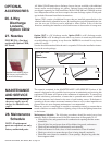
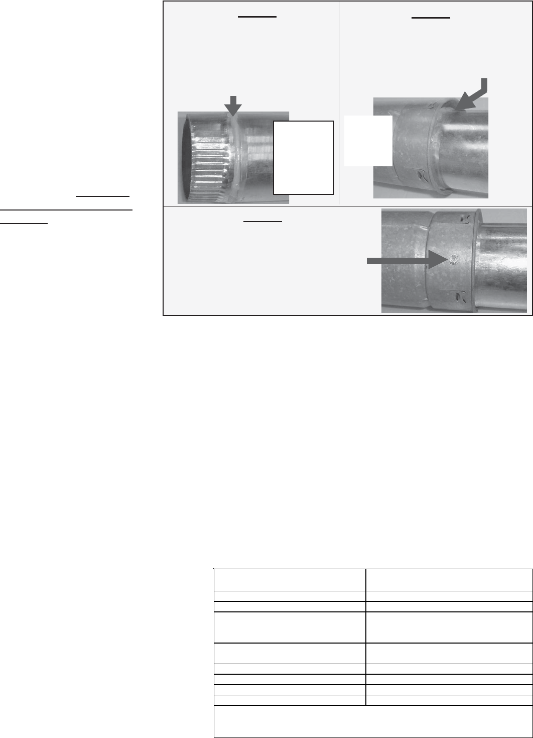
FIGURE 17C - Attaching
Double-Wall (Type B)
Terminal Pipe to a Single
Wall or Category III Vent
Pipe Run
Figure 17C -
STEP 1
On the single-wall pipe or Category
III pipe, place a continual
1/4 inch bead of silicone sealant
around the circumference.
Do STEP 2 immediately after
STEP 1.
Figure 17C -
STEP 2
Insert the pipe with the sealant into the
inner pipe of the double-wall pipe until
the bead of sealant contacts the inner
pipe creating a sealed joint.
Figure 17C - STEP 3
Spaced equally around the double-wall
pipe, drill three small holes below the
sealant ring. Insert 3/4 inch long
sheetmetal screws to secure the joint. Do
not over tighten screws.
Vent
Pipe
with
Sealant
Double-
Wall
Pipe
Single-
Wall or
Category
III Vent
Pipe
4) Joints and Sealing
(cont’d)
The vent terminal pipe must be either Category III vent pipe or double-wall (Type
B). Heaters must be equipped with a Reznor vent cap, a Type L Breidert Air-x-
hauster® vent cap or equivalent. A different style vent cap could cause nuisance
problems or unsafe conditions. The vent cap must be the same diameter as the vent
pipe.
See the clearance table below and FIGURE 18 for requirements of a horizontal
vent terminal. See FIGURE 19 for requirements of vertical vent termination.
Structure
Minimum Clearances for Vent Termination
Location (all directions unless specified)
Forced air inlet within 10 ft (3.1M) 3 ft (0.9M) above
Combustion air inlet of another appliance 6 ft (1.8M)
4 ft (1.2M) horizontally
4 ft (1.2M) below
1 ft (305mm) above
U.S. - 4 ft (1.2M) horizontally
Canada - 6 ft (1.8M) horizontally)
Gas regulator * U.S. - 3 ft (0.9M); Canada - 6 ft (1.8M)
Adjoining building or parapet 6 ft (1.8M)
Adjacent public walkways 7 ft (2.1M) above
Grade (ground level) 1 ft (305mm) above**
*Do not terminate the vent directly above a gas meter or service regulator.
Electric meter, gas meter*, gas regulator*,
and relief e
q
ui
p
ment
** Consider local snow depth conditions. The vent must be at least 6” (152mm) higher than
anticipated snow depth.
Door, window, or gravity air inlet (any
building opening)
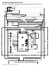
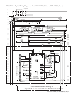
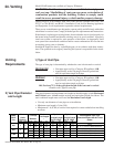
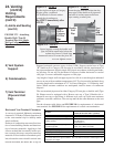
24. Venting
(cont’d)
Venting
Requirements
(cont’d)