


Form RZ-NA-I-LDAP, P/N 207733 (Rev 2), Page 13
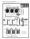
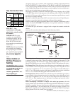
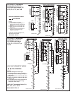
All electrical wiring and connections, including electrical grounding MUST be made
in accordance with the National Electric Code ANSI/NFPA No. 70 (latest edition) or,
in Canada, with CSA Standard C22.1. In addition, the installer should be aware of
any local ordinances or gas company requirements that might apply.
Check the rating plate on the heater for the supply voltage and current requirements.
A dedicated line voltage supply with disconnect switch should be run directly from
the main electrical panel to the heater. All external wiring must be within approved
14. Electrical
Supply and
Connections
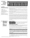
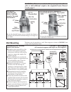
13. Burners
Each heat section in this heater has a one-piece TCORE
2
®
burner assembly (U.S.
Patent No. 6,889,686) designed to provide controlled flame stability without lifting or
flashback with either natural or propane gas.
The burner can be removed as a unit for inspection or service; see Maintenance
Section for removal instructions.
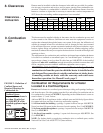
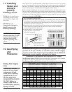
High Altitude
Capacity Changes
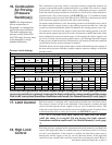
The input and/or the capacity of the heater changes with the derate. The tables below
list inputs and capacities at altitudes from sea level to 10,000 ft (3045M) for the U.S.
and to 4500 ft (1373M) for Canada.
Normal
Input
Thermal Output
Capacity
Mi nimum
Input
Normal
Input
Thermal Output
Capacity
Mi nimum
Input
Normal
Input
Thermal Output
Capacity
Minimum
Input
Feet Meters
0 - 2000 0 - 610 400000 332000 300000 800000 664000 400000 1200000 996000 400000
2001 - 3000 611 - 915 376000 312080 282000 752000 624160 376000 1128000 936240 376000
3001 - 4000 916 - 1220 368000 305440 276000 736000 610880 368000 1104000 916320 368000
4001 - 5000 1221 - 1525 360000 298800 270000 720000 597600 360000 1080000 896400 360000
5001 - 6000 1526 - 1830 352000 292160 264000 704000 584320 352000 1056000 876480 352000
6001 - 7000 1831 - 2135 344000 285520 258000 688000 571040 344000 1032000 856560 344000
7001 - 8000 2136 - 2440 336000 278880 252000 672000 557760 336000 1008000 836640 336000
8001 - 9000 2441 - 2745 328000 272240 246000 656000 544480 328000 984000 816720 328000
9001 - 10000 2746 - 3045 320000 265600 240000 640000 531200 320000 960000 796800 320000
Normal
Input
Thermal Output
Capacity
Mi nimum
Input
Normal
Input
Thermal Output
Capacity
Mi nimum
Input
Normal
Input
Thermal Output
Capacity
Minimum
Input
Feet Meters
0 - 2000 0 - 610 400000 332000 300000 800000 664000 400000 1200000 996000 400000
2001 - 4500 611 - 1373 360000 298800 270000 720000 597600 360000 1080000 896400 360000
BTUH Inputs & Capacities by Altitude in the UNITED STATES for Model LDAP
BTUH Inputs & Capacities by Altitude in the CANADA for Model LDAP
Size 400 Size 800 Size 1200
Altitude
Altitude
Size 800 Size 1200Size 400
Supply Wiring
4. Turn up the thermostat. Cycle the burners once or twice to properly seat the
adjustment spring in the valve.
Re-check the pressure(s). When the outlet pressure is right for the installation,
remove the manometer and replace the cap.
Check for leak at the pressure tap fitting.
5. If installing a Model LDAP 800, repeat the adjustment at the second single-stage
gas valve. If installing a Model LDAP 1200, repeat the adjustment at the second
and third single-stage gas valves.
6. With the heater operating determine that the inlet pressure to the heater for
natural gas is between 5 and 13.5 inches w.c. and for propane between 10 and
13.5 inches w.c. Take this reading at the inlet pressure tap of the first gas valve.
If the inlet pressure is not within the specified range, the inlet pressure must be
corrected and Steps 3 - 5 repeated.
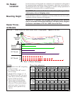
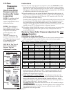
7. Find the High Altitude Adjustment label in the plastic bag that contained these
instructions. Using a permanent marker, fill-in the appropriate information from
the “BTUH Input & Capacity by Altitude” Table, below. Select a location for the
label on the outside of the heater main access panel so that it will be conspicuous
to anyone operating or servicing the heater. Be sure the surface is clean and dry
and adhere the label.