Form RZ-NA-I-LDAP, P/N 207733 (Rev 2), Page 7
10. Heater
Location
Use the clearances in Paragraph 8; the combustion air requirements in Paragraph 9;
the mounting height requirements, throw information, sound data, and location rec-
ommendations below; the weights in Paragraph 11; and the venting requirements in
Paragraph 24 to determine where to suspend the heater.
Mounting Height
Locate the heater so that it is a minimum of 15 feet (4.6M) above the floor and in
compliance with the clearances in Paragraph 8.
WARNING: If touched, the vent pipe and internal heater surfaces
that are accessible from outside the heater will cause burns. Suspend
the heater a minimum of 15 feet (4.6M) above the floor.
CAUTION: Do not locate the heater where it may be exposed to
water spray, rain, or dripping water.
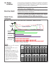
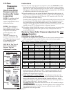
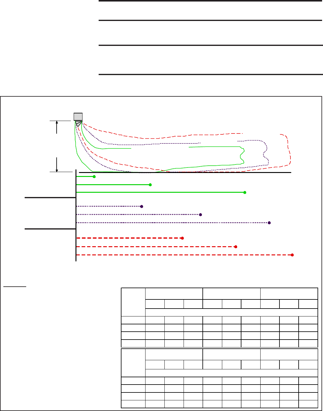
Heater Throw -
All Models
NOTES:
• X = Distance from “0” to beginning
of floor coverage.
• Y = Distance from “0” to end of
floor coverage.
• Length of floor coverage = Y - X.
• Z = Distance from “0” to the point
where the air velocity drops below
50 feet (15.2M) per minute.
• Throws listed are with standard
louvers facing one direction and
fully open. Throw pattern changes
with louver angle, 2-way louver
direction, and or optional 4-way
louvers.
Throw (feet and meters)
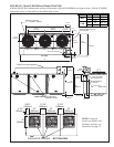
FIGURE 3 - Model LDAP Air Throw (Heat Mode @ High Speed) - Applies to All Sizes
0
= “Rear” of Heater Discharge
Mounting
Height
Standard Louvers
30° Nozzle
60° Nozzle
X
Y
Z
X
Y
Z
X
Y
Z
Standard
Louvers
30° Nozzle
60° Nozzle
0
XYZXYZXYZ
20
5 55 134 40 90 146 70 125 158
30
8 53 121 44 86 133 76 119 145
40
12 49 109 47 81 120 N/A N/A N/A
50
17 45 96 N/AN/AN/AN/AN/AN/A
XYZXYZXYZ
6.1
1.5 16.8 40.8 12.2 27.4 44.5 21.3 38.1 48.2
9.1
2.4 16.2 36.9 13.4 26.2 40.5 23.2 36.3 44.2
12.2
3.7 14.9 33.2 14.3 24.7 36.6 N/A N/A N/A
15.2
5.2 13.7 29.3 N/A N/A N/A N/A N/A N/A
Mounting
Height
(Meters)
Standard Louvers 30° Degree Nozzle 60° Degree Nozzle
Throw (meters)
Mounting
Height
(feet)
Standard Louvers 30° Degree Nozzle 60° Degree Nozzle
Throw (feet)


