


Form RZ-NA-I-LDAP, P/N 207733 (Rev 2), Page 10
Installing Louvers
NOTE: Do not install louvers
if installing a nozzle. Follow
the instructions shipped with
the nozzle.
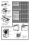
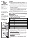
Louver Installation Instructions:
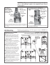
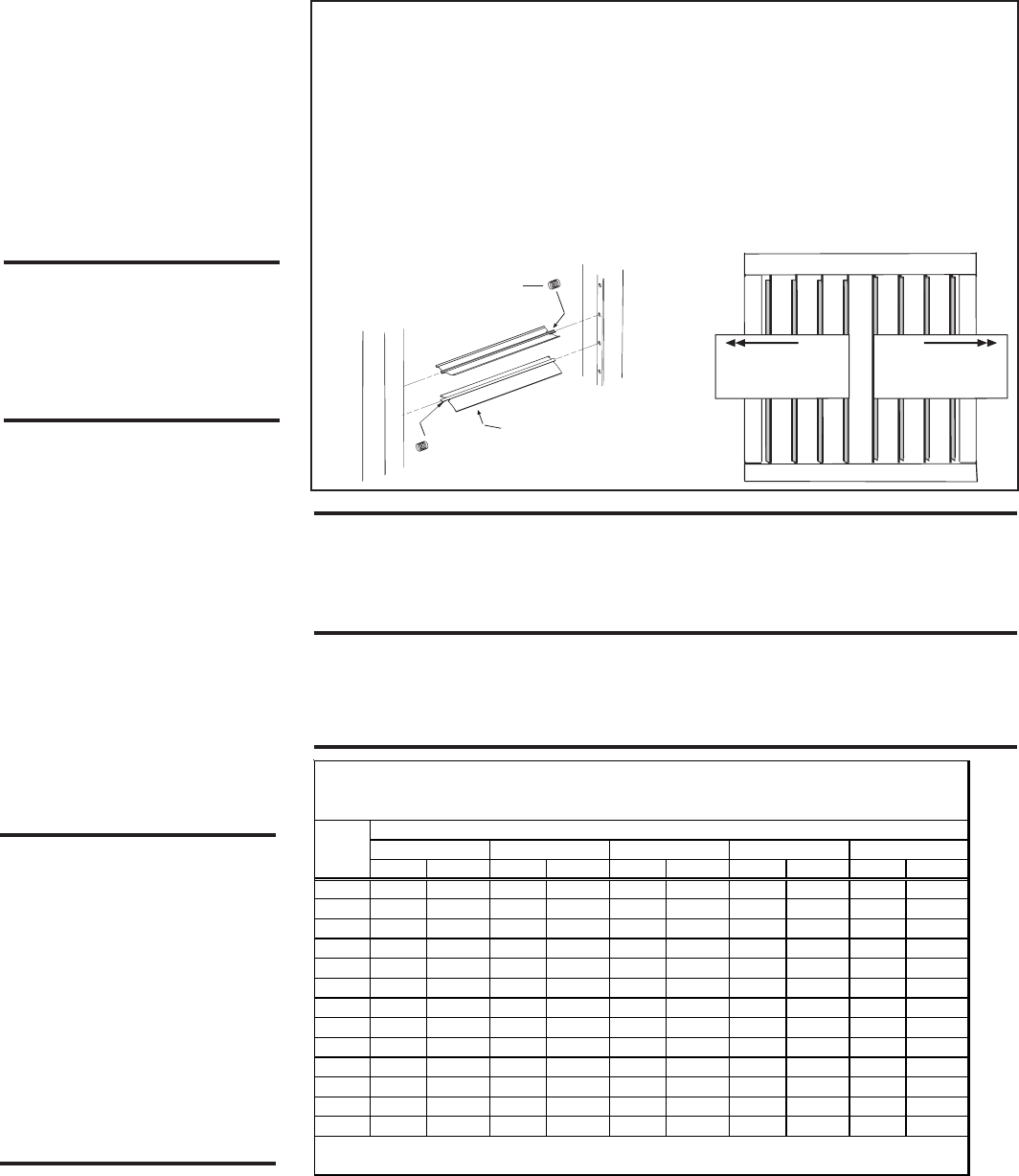
1) With the wider section of the louver facing out of the heater, place one of the compres-
sion springs over the tab on the notched end of a louver. The end of the louver with the
spring will fit in any direction in the square opening. How the louver turns depends on
which end of the louver is inserted first.
2) Depending on the throw pattern selected, push the louver tab with the spring into a
hole in the discharge opening and insert the louver tab on the other end into the
corresponding hole on the opposite side.
3) Continue until all louvers are installed.
Adjust the louvers to provide the
desired throw pattern.
Airflow direction;
springs are on
the upper end.
Airflow direction;
springs are on
the lower end.
Wider side of the louver
blade must always be
facing out of the heater.
Compression Spring
FIGURE 6 - Use
Compression Springs to
Install Louvers in the
Discharge Opening(s)
CAUTION: To avoid getting
burned, adjust louvers while
heater is not operating. If
adjusting louvers while
heater is operating, wear
gloves.
After the unit is suspended/mounted, install the air directional louvers or optional
nozzle. If an optional nozzle is being installed, follow the instructions included with
the nozzle. If a nozzle is not being used, install the louvers in the discharge opening(s).
Louvers and springs are in the hardware kit shipped with the heater.
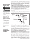
Before actually installing the louvers, note the louver curve and determine how the
louvers should be positioned to provide the optimal throw pattern. Opening is square
so louvers may be installed either horizontal or vertical. Louvers may be installed
with the curve all the same direction (either way) or the right half one way and left
the other as illustrated in FIGURE 6.
Airflow direction depends on
how the louvers are installed.
WARNING: This appliance is equipped for a maximum gas supply
pressure of 1/2 psi, 3.5 kPa, or 14 inches water column. Supply
pressure greater than 1/2 psi requires installation of an additional
lockup-type service regulator external to the heater.
WARNING: PRESSURE TESTING SUPPLY PIPING
Test Pressures Above 1/2 PSI: Disconnect the heater and manual valve from the
gas supply line which is to be tested. Cap or plug the supply line.
Test Pressures Below 1/2 PSI: Before testing, close the manual valve on the heater.
12. Gas Piping
and
Pressures
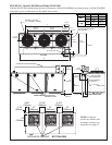
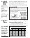
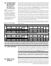
Sizing Gas Supply
Line
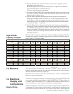
Capacity of Piping
- Cubic Feet per Hour based on 0.3" w.c. Pressure Drop
Specific Gravity for Natural Gas -- 0.6 (Natural Gas -- 1000 BTU/Cubic Ft)
Specific Gravity for Propane Gas -- 1.6 (Propane Gas -- 2550 BTU/Cubic Ft)
Length Diameter of Pipe
of 1" 1-1/4" 1-1/2" 2" 2-1/2"
Pipe Natura
l
Propane Natural Propane Natura
l
Propane Natura
l
Propane Natural Propane
20' 350 214 730 445 1100 671 2100 1281 3300 2013
30' 285 174 590 360 890 543 1650 1007 2700 1647
40' 245 149 500 305 760 464 1450 885 2300 1403
50' 215 131 440 268 670 409 1270 775 2000 1220
60' 195 119 400 244 610 372 1105 674 1850 1129
70' 180 110 370 226 560 342 1050 641 1700 1037
80' 170 104 350 214 530 323 990 604
1600
976
90' 160 98 320 195 490 299 930 567 1500 915
100' 150 92 305 186 460 281 870 531 1400 854
125' 130 79 275 168 410 250 780 476 1250 763
150' 120 73 250 153 380 232 710 433 1130 689
175' 110 67 225 137 350 214 650 397 1050 641
200' 100 61 210 128 320 195 610 372 980 598
Note: When sizing supply lines, consider possibilities of future expansion and increased requirements.
Refer to National Fuel Gas Code for additional information on line sizing.
WARNING: All com-
ponents of a gas supply
system must be leak
tested prior to placing
equipment in service.
NEVER TEST FOR
LEAKS WITH AN OPEN
FLAME. Failure to
comply could result in
personal injury, property
damage or death.
11. Installing
Heater and
Louvers
(cont’d)