


Form RZ-NA-I-LDAP, P/N 207733 (Rev 2), Page 33
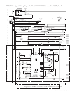
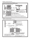
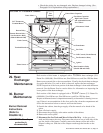
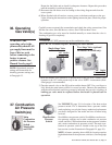
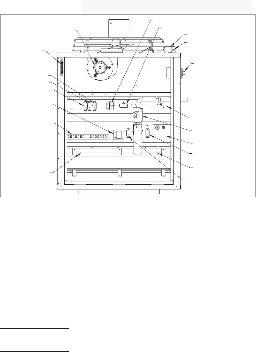
Fan
Motor
Heat Section Pressure Switch
Venter Motor Capacitor
Fan Motor Capacitor
High Limit Control
and Adjustable Destrat
Fan Control
Disconnect Switch
Transformer
Gas Valve
DSI Control (Circuit Board)
Fan Permissive Relay
Ignitor
Heat Permissive Relay
(Models 800 and 1200)
Flame Sensor
Terminal Boards
Limit Control
Vent Permissive Relay
(Models 800 and 1200)
Remote Destrat Relay
Destrat Relay
24V Thermostat
Terminal Board
Burner Assembly
Venter Motor
FIGURE 22 - Location of Controls
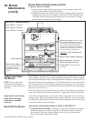
30. Burner
Maintenance
Each section of this heater is equipped with a TCORE
2
®
burner (U.S. Patent No.
6,889,686). Size 400 has one; Size 800 has two; and Size 1200 has three.
Inspect each burner/control compartment annually to determine if cleaning is neces-
sary. If there is an accumulation of dirt, dust, and/or lint, clean the compartment and
follow the instructions below to remove and clean the burner.
1. Outside the cabinet, shut the gas supply off at the manual valve ahead of the
union.
2. Turn off electric supply.
3. Disconnect the gas supply at the union outside of the cabinet.
4. Remove the access panel.
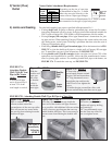
5. Disconnect the Gas Train and Move It Out of the Way - At the gas valve,
mark and disconnect the wires. Disconnect the union on one or both sides of the
gas line inside of the heater. Carefully remove the burner orifice and orifice
adapter locking nut. Slide the orifice adapter out through the bracket on the
burner.
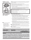
Burner Removal
Instructions
(Refer to
FIGURE 23.)
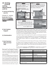
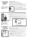
29. Heat
Exchanger
Maintenance
Each section of this heater is equipped with a TCORE
2
®
heat exchanger (U.S.
Patent No. 6,889,686). Size 400 has one; Size 800 has two; and Size 1200 has three.
Remove any external dirt or dust accumulation. Visually check each heat exchanger
for cracks and holes. If a crack or hole is observed, replace the heat exchanger.
NOTE: Inspection of the lower portion of the heat exchanger is done with the burner
removed. See the Burner Service section below for information on inspecting the
lower portion of the heat exchanger.
CAUTION: Use of eye
protection is
recommended.
• Check the wiring for any damaged wire. Replace damaged wiring. (See
Paragraph 14 for replacement wiring requirements.)