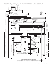
Form RZ-NA-I-LDAP, P/N 207733 (Rev 2), Page 21
The main operating gas valve(s) is powered by the 24-volt control circuit through the
thermostat and safety controls. The gas valve is of the diaphragm type providing
regulated gas flow preset at the factory. (For location, see FIGURE 22, page 33.)
WARNING: The operating valve is the prime safety shutoff. All gas
supply lines must be free of dirt or scale before connecting the heater
to ensure positive closure. See Hazard Levels, page 2.
Each heat section in the heater has a fan motor. Each fan motor(s) is equipped with
thermal overload protection of the automatic reset type. Should the motor(s) refuse to
run, it may be because of improper current characteristics. Make certain that the cor-
rect voltage is available at the motor(s).
Fan Motor Wiring
White = Neutral
Black = High (Heat Speed)
Blue = Medium (Destratification Speed, Factory Wired)
Red = Low (Optional Destratification Speed, Field Wired)
21. Gas Valve(s)
Lockout
Undesired Flame - If flame is sensed longer than 20 seconds while the gas valve is de-
energized, the control shall energize the heat section venter motor, the main venter motor,
and the fan motor on heat speed. When flame is no longer sensed, the heat section venter
motor and main venter motor will run through postpurge, and the fan motor will run
through the selected heat fan off delay time. The control will do a soft lockout, but will
still respond to open limit and flame. The FLAME (yellow) LED shall flash rapidly when
lockout is due to undesired flame.
Gas Valve Relay Fault - If the control senses the gas valve as energized for more than
one second when the control is not attempting to energize the gas valve, or the gas valve
is sensed as not energized when it is supposed to be energized, then the control will
lockout with the green LED off. The control assumes either the contacts of the relay
driving the gas valve have welded shut, or the sensing circuit has failed. The heat section
venter motor is forced off to open the heat section pressure switch to stop gas flow unless
flame is present.
If the gas valve was sensed as closed when it should be open, and has not de-energized
after the heat section venter motor and main venter motor was shutoff for 15 seconds,
then the heat section venter motor and main venter motor are re-energized to vent the
unburned gas.
Soft Lockout - The control shall not initiate a call for heat or call for continuous fan while
in lockout. The control will still respond to an open limit and undesired flame. Lockout
shall automatically reset after one hour. Lockout may be manually reset by removing
power from the control for more than one second or removing the thermostat call for heat
for more than one and less than 20 seconds.
Hard Lockout (Green LED - steady off) - If the control detects a fault on the control
board, the status LED will be de-energized, and the control will lockout as long as the
fault remains. A hard lockout will automatically reset if the hardware fault clears.
Power Interruption - During a momentary power interruption or at voltage levels below
the minimum operating voltage (line voltage or low voltage), the system will self-recover
without lockout when voltage returns to the operating range.
Power interruptions of less than 80mS shall not cause the control to change operating
states. Power interruptions greater than 80mS may cause the control to interrupt the cur-
rent operating cycle and re-start. Power interruption during a heat cycle may trip the
manual reset high limit switch.
Fault Modes
22 Fan Motor(s)
• Size 400 has 1 valve.
• Size 800 has 2 valves.
• Size 1200 has 3 valves.
• Size 400 has 1 fan motor.
• Size 800 has 2 fan motors.
• Size 1200 has 3 fan motors.


