


Form RZ-NA-I-LDAP, P/N 207733 (Rev 2), Page 31
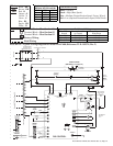
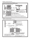
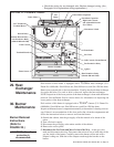
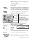
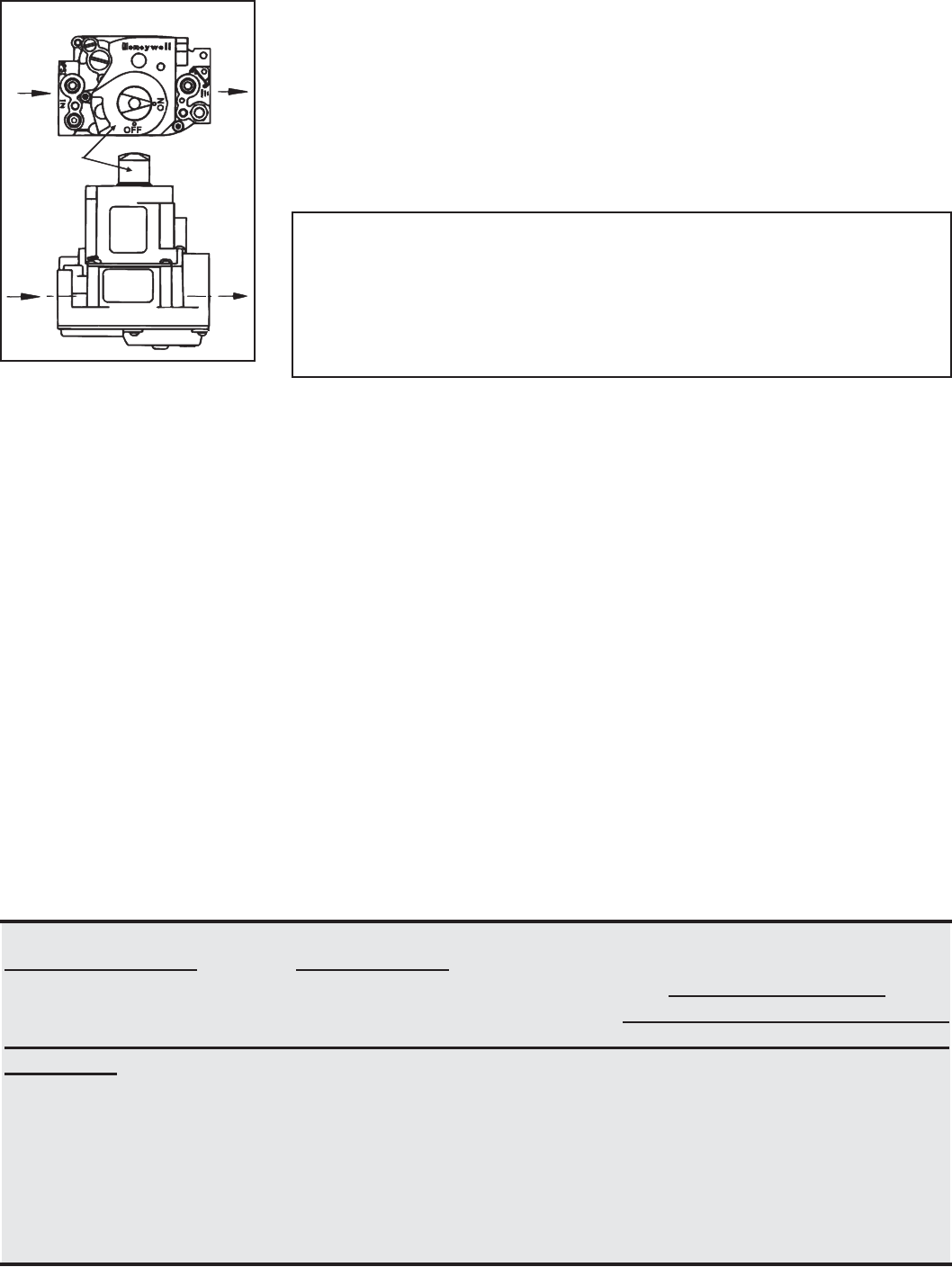
Gas Control
Knob
(shown in the
ON position)
Gas
Flow
Gas
Flow
Top View
Side View
FIGURE 20 - Gas Valve
ON/OFF Control Knob
Check installation
after startup:
Vent System Testing Procedure
1. Seal any unused openings in the venting system.
2. Inspect the venting system for proper size and horizontal pitch, as required in
the National Fuel Gas Code, ANSI Z223.1 or CSA B149.1 and B149.2,
Installation Code for Gas Burning Appliances and Equipment, and this
manual. Determine that there is no blockage or restriction, leakage, corrosion
or other deficiencies that could cause an unsafe condition.
3. In so far as practical, close all building doors and windows and all doors
between the space where the heater is and other spaces of the building. Turn
on exhaust fans so they shall operate at maximum speed. Do not operate a
summer exhaust fan.
4. Light the heater following the lighting instructions. Adjust the thermostat for
continued operation. Verify that combustion products are venting properly.
After determining that the heater vents properly, return doors, windows, and
exhaust fans to their previous conditions. If improper venting is observed, the
venting system must be corrected.
With the heater in operation, measure valve outlet gas pressure. If operated at
high altitude, adjust outlet gas pressure for altitude. See information and instruc-
tions in Paragraph 12.
Using the thermostat, turn the heater off and on, pausing two minutes between
each cycle. Observe for smooth ignition.
NOTE: If the appliance does not operate, follow the instructions "To Turn Off Gas
to Appliance" printed below (and on the Operating Label on the heater) and call
your service technician.
10. Thermostat calls for heat, energizing the venter motor(s).
11. The main combustion air pressure switch (Sizes 800 and 1200) and each heat
section pressure switch close, firing the heater.
12. Burner flame is sensed and in 30 seconds after the gas valve is energized, the
fan motor(s) is energized.
13. If the flame is extinguished during the main burner operation, the integrated
control system closes the main valve and must be reset by interrupting power
to the control circuit. (See lighting instructions on the heater.).
TO TURN OFF GAS TO THE APPLIANCE
1) Set thermostat to lowest setting
2) If service is to be performed, turn off all electric power to the appliance.
3) Open the access door(s).
4) Turn the gas control knob(s) clockwise to "OFF". Do not force.
5) Close the access door(s).
DANGER: The gas burner in this gas-fired equipment is designed and equipped to provide safe controlled
complete combustion. However, if the installation does not permit the burner to receive the proper supply
of combustion air, complete combustion may not occur. The result is incomplete combustion which
produces carbon monoxide, a poisonous gas that can cause death. Safe operation of indirect-fired gas
burning equipment requires a properly operating vent system that vents all flue products to the outside
atmosphere. FAILURE TO PROVIDE PROPER VENTING WILL RESULT IN A HEALTH HAZARD
WHICH COULD CAUSE SERIOUS PERSONAL INJURY OR DEATH.
Always comply with the combustion air requirements in the installation codes and in Paragraph 9.
Combustion air at the burner should be regulated only by manufacturer-provided equipment. NEVER
RESTRICT OR OTHERWISE ALTER THE SUPPLY OF COMBUSTION AIR TO ANY HEATER.
Heaters installed in a confined space must be supplied with air for combustion as required by Code and
in Paragraph 9 of this heater installation manual. MAINTAIN THE VENT SYSTEM IN
STRUCTURALLY SOUND AND PROPER OPERATING CONDITION.
Place the "Owner's Envelope"
containing the Limited
Warranty, this booklet, and
any control or optional
information in an accessible
location near the heater.
Follow the instructions on the
envelope.