


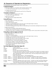
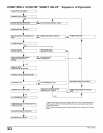
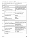
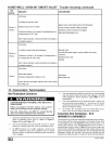


HONEYWELL SV9541M "SMART VALVE" Trouble shooting continued
LED
INDICATES CHECK/REPAIR
STATUS
Soft Lockout.
6 Flashes+
3 Flashes
6 Flashes+
4 Flashes
7Flashes
Last failure was pressure switch
Maximum recycle count exceeded
Combustion air blower isde-energized, Circulating blower isde-
energized after the "OFF" delay.
After 5-minute delay time, control system will reset and initiate a
new ignition sequence,
Soft Lockout.
Last failure was limit circuit opened during run.
Combustion air blower is de-energized, Circulating blower is
de-energized after the "OFF" delay.
After 5-minute delay time, control system will reset and initiate a
new ignition sequence,
Soft Lockout.
Blowerfailure(typical)
Limittriptooklongerthan2minutestoreset.
System will start a new ignition sequence after 1 hour, if call for
heat still present.
Ignition system control switch must be inthe ON position.
Pressure switches operation, tubing, and wiring.
Restrictions in furnace air intake or vent piping.
High winds blowing against vent.
Main limit switch.
Limit and rollout switch wiring is in good condition and securely
connected.
Restriction in duct work.
Dirty filter
Deadblower.
Blockedductwork.
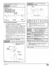
11. Concentric Termination
Vent Termination Clearances
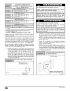
CARBON MONOXIDE POISONING, FIRE AND EXPLO-
SION HAZARD
Failure to properly vent this furnace can result in
death, personal injury and/or property damage.
Inlet and outlet pipes may NOT be vented directly
above each other (standard vent terminals).
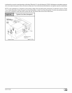
1. Determine termination locations based on clearances spe-
cified in following steps and as shown in Figure 7,
Figure 44 through Figure 49.
2. The vent termination must be located at least 12" above
ground or normally expected snow accumulation levels.
3. Do NOT terminate over public walkways. Avoid areas
where condensate may cause problems such as above
planters, patios, or adjacent to windows where steam may
cause fogging.
4. The vent termination shall be located at least 4' horizontally
from any electric meter, gas meter, gas regulator, and any
relief equipment. These distances apply ONLY to U.S.
installations.
5. The vent termination is to be located at least 3' above any
forced air inlet located within 10' ; and at least 10' from a
combustion air intake of another appliance, except another
direct vent furnace intake.
6. In Canada, the Canadian Fuel Gas Code takes prece-
dence over the preceding termination instructions.
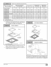
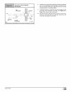
Concentric Vent Termination - Kit #
NAHA001CV & NAHA002CV
These kits are for vertical or horizontal termination of the combus-
tion air inlet and the exhaust vent pipes on Category IV gas-fired
condensing furnaces. The NAHAO01CV kit can be used for 3" di-
ameter pipe systems. The NAHAOO2CV kit can be used for 2"
diameter pipe system. Refer to Table 10 for the correct pipe size
for the furnace. Both the combustion air inlet and the exhaust vent
pipes must attach to the termination kit. The termination kit must
terminate outside the structure and must be installed per the
instructions outlined below for vertical or horizontal termination.
[_ 44001111400