


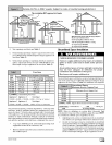
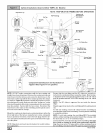

HorizontalLeftInstallations (Dual Certified *9MPD-A4 Models)
Horizontal Trap Connection
NOTE: TRAP MUST BE PRIMED BEFORE OPERATION
ipe Combustion Air
Pipe,(optional)
5/16" OD
Rubber
Model shown with two
pressure switches
"Clamp ears"
Pointed OUT
Preassembleand
insertintofurnace
Supply
Air
PVCVent
Extension Pipe
Vent Pipe
Grommet
Vent Fitting
& Clamps Yellow RubberCouplings
Plastic & Clamps 90° Elbow
& Clamps Plastic Cap
DRAIN SIDE VIEW
11" Section
& Clamps 2" PVCPipe _tate downward
(Field Supplied) DrainLine_: _
angled5° to10° also.
Condensate
Trap & Gasket
Blower
Transition
3/4" Hose & Clamps
Return Air
25-24-12
Single Pressure Switch
Connections on
All models except 125
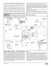
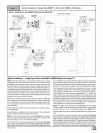
Horizontal Left Installations - (Dual Certified *9MPD) (See Figure 10)
Note: DO NOT make hose connections until the hose routing and
lengths have been determined. Remove the condensate trap and
drain hoses from the furnace and secure the drain hoses to the
drain stubs on the trap with the hose clamps (position the clamps
as shown in Figure 10). Install the condensate trap/hose assem-
blyto the furnace casing. Hook one side ofthe"clamp ears" on the
drain stub through the hole in the casing and push the condensate
trap into position. Secure with the two screws. Reconnect the
drain hoses to the stubs on the vent fitting and the plastic transi-
tion and secure with the clamps.
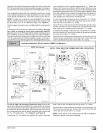
Relocate the plastic cap and clamp from the vertical transition
drain stub to the horizontal transition drain stub on the conden-
sate drain trap. Secure the clamps tightly to prevent condensate
leakage. Do not change the cap and clamp on the vent drain stub.
Mount the condensate drain trap in a vertical position to the left
side of the furnace using the two screws and gasket that are pro-
vided. Note: The condensate trap will be located under the fur-
nace in a vertical position when the furnace is placed horizontally
on the left side. If needed, remove the hole plugs from the furnace
side panel and relocate to the open set of holes in the opposite
side panel.
NOTE: All gaskets and seals must be in place for sealed combus-
tion applications.
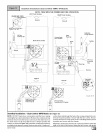
Remove the 90 ° elbow and vent fitting from the combustion blow-
er by loosening the clamps on the vent fitting. Connect the 90 ° el-
bow to the combustion blower using the rubber coupling and
cla raps. Note for proper alignment of the vent pipe through the fur-
nace, the 90 ° elbow must be installed with the "HORIZONTAL"
lettering on the 90 ° elbow facing out. Connect a 11" section of 2"
PVC pipe (field supplied) to the 90 ° elbow using the rubber cou-
pling and clammps. The PVC pipe will extend through the top pa n-
el a bout 11/2". Connect the vent fitting to the end of the 11" section
of PVC pipe using the clamp.
NOTE: The 90 ° elbow is approved for use inside the furnace
ONLY.
NOTE: The vent fitting MUST be installed with the airflow marking
arrow pointed toward the vent pipe, with the drain stub at a 5° to
10 ° downward slope.
Plug the upper drain stub on the vent fitting with the yellow plastic
cap.
Connect the PVC vent extension pipe to the vent fitting. This pipe
has a built-in channel to assist vent condensate disposal.
Align the arrow on the PVC pipe with the airflow marking arrow on
the vent fitting. See label on the PVC pipe for proper installation.
This pipe may only be shortened if an elbow is used to connect the
[_ 44001111400