


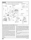
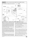
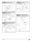

Forleftsidemountedcondensatetrap,connectthe3/4"ODrub-
berhosewiththe90°bendtothelargedrainstubontheconden-
satetrapandsecurewitha3/4"clamp.
Routethehosetothedrainstubonthebottomoftheplastictransi-
tionbox.Cutoffexcesshoseanddiscard.Connectthehosetothe
drainstubonthetransitionandsecurewitha3/4"clamp.
Forrightsidemountedcondensatetrap,connectthe3/4"ODrub-
berhosewiththe90°bendtothebottomoftheplastictransition
boxandsecurewitha3/4"clamp.
Routethehosetothelargedrainstubonthecondensatepump.
Cutoffexcesshoseanddiscard.Connectthehosetothedrain
stubonthecondensatetrapandsecurewitha3/4"clamp.
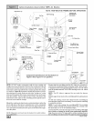
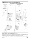
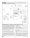
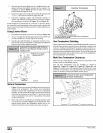
Upflow Installations (Single Pipe N9MP1 & Direct Vent N9MP2-A4 Models)
RIGHTSideVenting NOTE: TRAP MUST BE PRIMED BEFORE OPERATION
Supply Air
Models shown
have two
pressure switch
N9MP; ONLY
(Rotate 180° for Left Side)
Combustion Blower
Screws (4)
Single Pressure Switch
Connections on all
models except 125
Combustion Blower
(Rotate100°
DRAIN SIDE VIEW
5° to 10°
3uiit-in channel will
angled 5° to 10° also.
Vent
Drain
25-24-05
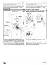
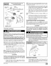
For left side or right side mounted condensate trap, the pres-
sure tap on the condensate trap MUST be connected to the un-
used pressure tap located on the upper right hand corner of the
plastic transition box. Remove the plastic caps from the pressure
taps on the condensate trap and the plastic transition and connect
with the 5/16" OD rubber hose. (See Figure 13 and Figure 14)
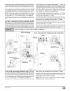
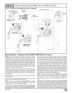
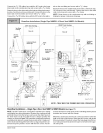
Connect the 5/8" OD rubber hose with the 90 ° bend to the lower
drain stub on the vent fitting and secure with a 5/8" clamp.
Route the hose to the smaller drain stub on the condensate trap.
Cut off excess hose and discard. Connect the hose to the drain
stub on the trap and secure with a 5/8" clamp.
NOTE: Route hoses to the condensate trap with no kinking or
binding for proper condensate drainage.
[_ 44001 111400