


13.The vent outlet MUST be installed to terminate in the same
atmospheric pressure zone as the combustion air inlet.
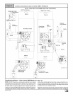
14. The vent system can be installed in an existing unused
chimney provided that:
• Both the exhaust vent and air intake run the length of the
chimney.
• No other gas fired appliance or fireplace (solid fuel) is
vented into the chimney.
• The top of the chimney MUST be sealed flush or crowned
upto seal against rain or melting snow so ONLY the piping
protrudes.
• The termination clearances shown in Figure 7 are main-
tained.
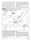
15.
Furnace applications with vertical vents requiring vent di-
ameter increaser fittings must have increaser fittings
installed in vertical portion of the vent. Condensate will be
trapped in the vent if the vent diameter is increased prior to
having an elbow turned upward. This could cause nui-
sance tripping of the pressure switch.
Piping Insulation Guidelines
NOTE: Use closed cell, neoprene insulation or equivalent. If Fi-
berglass or equivalent insulation is used it must have a vapor bar-
rier. Use R values of 7 up to 10', R-11 if exposure exceeds 10'. If
Fiberglass insulation is used, exterior to the structure, the pipe
MUST be boxed in and sealed against moisture.
When the vent or combustion air pipe height above the roof
exceeds 30", or if an exterior vertical riser is used on a hori-
zontal vent to get above snow levels, the exterior portion
MUST be insulated.
When combustion air inlet piping is installed above a sus-
pended ceiling, the pipe MUST be insulated with moisture
resistant insulation such as Armaflex or other equivalent
type of insulation.
Insulate combustion air inlet piping when run in warm, hu-
mid spaces such as basements.
Sizing Combustion Air and Vent Pipe
Consult Table 3 or Table 4 to select the proper diameter exhaust
and combustion air piping. Exhaust and combustion air piping is
sized for each furnace Btuh size based on total lineal vent length
(on inlet or outlet side), and number of 90 ° elbows required. Two
45 ° elbows can be substituted for one 90 ° elbow. The elbow or el-
bows used for vent termination outside the structure ARE
counted, including elbows needed to bring termination above ex-
pected snow levels. The elbow inside the furnace on the *9MPD
IS NOT included in the count.
Pipe Diameter Table
N9MP1 & *9MPD Models
50,000, 75,000 & 80,000 Btuh Furnaces
40' & (5) 90° elbows with 2" PVC pipe or
70' & (5) 90° elbows with 3" PVC pipe
100,000 Btuh Furnace
40' & (5) 90° elbows with 3" PVC pipe or
70' & (5) 90° elbows with 3" PVC pipe &
Long Vent Kit (See Tech. Manual)
125,000 Btuh Furnace
40' & (5) 90° elbows with 3" PVC pipe
Elbows are DWV Long Radius Type for 2" and 3" vents,
If more than five elbows are required, reduce the length of
both the inlet and exhaust pipes 5' for each additional elbow
used.
NOTE: It is allowable to use larger diameter pipe and fitting than
shown in the tables but not smaller diameters than shown.
Pipe Diameter Table
N9MP2 Models
50,000 & 80,000 Btuh Furnaces
40' & (5) 90° elbows with 2" PVC pipe or
70' & (5) 90° elbows with 3" PVC pipe
75,000 Btuh Furnaces
25' & (3) 90° elbows with 2" PVC pipe or
40' & (5) 90° elbows with 2" PVC pipe &
Long Vent Kit (See Tech. Manual) or
70' & (5) 90° elbows with 3" PVC pipe
100,000 Btuh Furnace
40' & (5) 90° elbows with 3" PVC pipe or
70' & (5) 90° elbows with 3" PVC pipe &
Long Vent Kit (See Tech. Manual)
125,000 Btuh Furnace
40' & (5) 90° elbows with 3" PVC pipe
Elbows are DWV Long Radius Type for 2" and 3" vents.
If more than five elbows are required, reduce the length of
both the inlet and exhaust pipes 5' for each additional elbow
used.
For "Concentric Termination Kit" Venting table, see
"Section 11" in this manual.
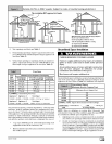
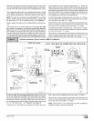
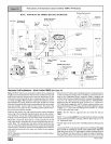
Vent Termination Clearances
CARBON MONOXIDE POISONING, FIRE AND EXPLO-
SION HAZARD
Inlet and outlet pipes may NOT be vented directly above
each other.
Failure to properly vent this furnace can result in death,
personal injury and/or property damage.
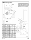
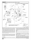
1. Determine termination locations based on clearances spe-
cified in following steps and as shown in Figure 7,
Figure 19, through Figure 27.
For "Concentric Termination Kit" clearances, see Figure 45,
Figure 46, Figure 47, Figure 48 and Figure 49 in "Section 10"
in this manual.
2. The vent termination must be located at least 12" above
ground or normally expected snow accumulation levels.
[_ 44001 111400