


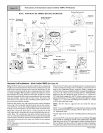
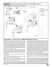

Horizontal Right Installations (Single Pipe & Direct Vent N9MP1 & N9MP2-A4 Models)
NOTE: TRAP MUST BE PRIMED BEFORE OPERATIONveni_ipls_lv__Plastic
Cap
\
Vent Fitting
& Clamps
Return
Air
\
\
518" Hose &\
%
Clamps _
Modelsshownhave__
twopressureswitches
Horizontal Trap Connection
Plastic Pressure 3/4" Hose
"Clamp ears" Cap Switch, Transition ps
Pointed OUT
Condensate
Trap & Gasket Switch, Blower
Combustion
Air Pipe,
N9MP2 ONLY
Inlet
Supply
Air
dwg25-23-59a
Pressure Switch
Hose, Transition
Preassemble
and insert
into furnace
Drain Line
Single Pressure Switch
Connections on all
models except 125
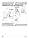
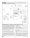
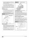
Horizontal Right Installations - (Single Pipe & DirectVent N9MP1 & N9MP2 Models) (SeeFigure16)
NOTE: DO NOT make hose connections until the hose routing
and lengths have been determined. Remove the condensate trap
and drain hoses from the furnace and secure the drain hoses to
the drain stubs on the trap with the hose clamps (position the
clamps as shown in Figure 16). Install the condensate trap/hose
assembly to the furnace casing. Hook one side of the "clamp ears"
on the drain stub through the hole in the casing and push the con-
densate trap into position. Secure with the two screws. Recon-
nect the drain hoses to the stubs on the vent fitting and the plastic
transition and secure with the clamps.
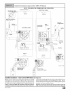
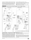
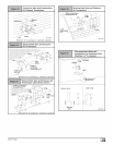
Relocate the plastic caps and clamps on the condensate drain
trap from the vertical drain stub to the horizontal drain stubs. Se-
cure the clamps tightly to prevent condensate leakage.
Mount the condensate drain trap in a vertical position to the right
side of the furnace using the two screws and gasket that are pro-
vided. Note: The condensate trap will be located under the fur-
nace in a vertical position when the furnace is placed horizontally
on the right side. If needed, remove the hole plugs from the fur-
nace side panel and relocate to the open set of holes in the oppo-
site side panel.
NOTE: All gaskets and seals must be in place for sealed combus-
tion applications.
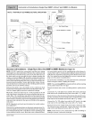
Ensure that the vent fitting is securely attached to the combustion
blower using the clamps.
NOTE: The vent fitting MUST be installed with the airflow marking
arrow pointed toward the vent pipe.
Plug the left drain stub on the vent fitting with the yellow plastic
cap.
Remove the pressure switch hose from the upper stub on the
plastic transition box.
Relocate the plastic ca ps on the stubs of the plastic transition from
the lower stubs to the upper stubs and secure tightly with the
clamps.
Route the pressure switch hose to the lower stub on the plastic
transition box. Cut off excess hose and discard. Connect the
pressure switch hose to the lower stub on the plastic transition
box. Ensure that the hose is routed above the stub on the transi-
tion box so that condensate does not collect in the hose. NOTE:
Failure to correctly install the pressure switch hose to the transi-
tion can adversely affect the safety control operation.
[_ 44001111400