


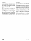
NOTE:Allgasketsandsealsmustbein place for sealed combus-
tion applications.
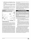
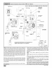
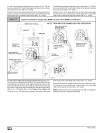
Remove the 90 ° elbow and vent fitting from the combustion blow-
er by loosening the clamps on the vent fitting. Connect the 90 ° el-
bow to the combustion blower using the rubber coupling and
cla raps. Note for proper alignment of the vent pipe through the fur-
nace, the 90 ° elbow must be installed with the "HORIZONTAL"
lettering on the 90 °elbow facing out. Connect the vent fitting to the
end of the 90 ° elbow using the clamp.
NOTE: The 90° elbow is approved for use inside the furnace
ONLY.
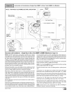
NOTE: The vent fitting MUST be installed with the airflow marking
arrow pointed toward the vent pipe, with the drain stub at a 5°to
10° downward slope.
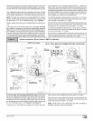
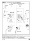
Plug the upper drain stub on the vent fitting with the yellow plastic
cap.
Connect the PVC vent extension pipe to the vent fitting. This pipe
has a built-in channel to assist vent condensate disposal.
Align the arrow on the PVC pipe with the airflow marking arrow on
the vent fitting. See label on the PVC pipe for proper installation.
This pipe may only be shortened if an elbow is used to connect the
PVC vent extension tube to field-installed vent pipe. Securely at-
tach the PVC vent extension pipe to the vent fitting with the clamp.
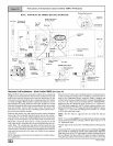
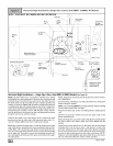
Remove the pressure switch hose from the upper stub on the
plastic transition box.
Relocate the plastic caps on the stubs of the plastic transition box
from the lower stubs to the upper stubs and secure tightly with the
clamps.
Route the pressure switch hose to the lower stub on the plastic
transition box. Cut off excess hose and discard. Connect the pres-
sure switch hose to the lower stub on the plastic transition box.
Ensure that the hose is routed above the stub on the transition box
sothat condensate does not collect in the hose. NOTE: Failure to
correctly install the pressure switch hose to the transition can ad-
versely affect the safety control operation.
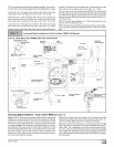
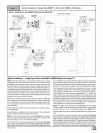
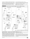
Connect the 3/4" OD rubber hose with the 90 ° bend to the large
drain stub on the condensate trap and secure with a 3/4" clamp.
Route the hose to the drain stub on the bottom of the plastic tran-
sition box. Cut off excess hose and discard. Connect the hose to
the drain stub on the transition and secure with a 3/4" clamp.
Connect the 5/8" OD rubber hose with the 90 ° bend to the lower
drain stub on the vent fitting and secure with a 5/8" clamp.
Route the hose to the smaller drain stub on the condensate trap.
Cut off excess hose and discard. Connect the hose to the drain
stub on the trap and secure with a 5/8" clamp.
NOTE: Route hoses to the condensate trap with no kinking or
binding for proper condensate drainage.
E_ 44001 111400