


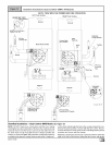
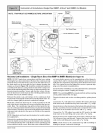
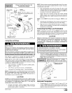
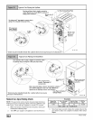

Proper Sealing Procedure for
Combustion Blower
RubberCoupling J ._ VentPipe
&Clamps--__ ____ _ _ (Top Panel Exit)
tPipe _ NOTE: The 90 ° elbow is ap-
proved for use inside the furnace
ONLY.
Vent Fitting
90° Elbow &Clamps
Combustion
Blower
Vent Extension _'_.
Pipe (Side Panel
Exit)
DRAIN SIDE VIEW
_/_'ia te downward
NOIF.guilt-inchannelwill
beangled5°to 10° also.
25-24-14
Joining Pipe and Fittings
NOTE: Stir the solvent cement frequently while using. Use a natu-
ral bristle brush or the dauber supplied with the cement. The prop-
er brush size is one inch.
2. After checking pipe and socket for proper fit, wipe socket
and pipe with cleaner-primer. Apply a liberal coat of primer
to inside surface of socket and outside of pipe. Do NOT al-
low primer to dry before applying cement.
3. Apply a thin coat of cement evenly in the socket. Quickly
apply a heavy coat of cement to the pipe end and insert
pipe into fittings with a slight twisting movement until it bot-
toms out.
NOTE: Cement MUST be fluid while inserting pipe. If NOT, recoat
pipe.
4. Hold the pipe in the fitting for 30 seconds to prevent the ta-
pered socket from pushing the pipe out of the fitting.
5. Wipe all excess cement from the joint with a rag. Allow 15
minutes before handling. Cure time varies according to fit,
temperature and humidity.
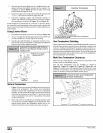
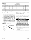
Connecting Vent Pipes and Termination
NOTE: Combustion air intake and vent MUST terminate in the
same atmospheric pressure zone. If installation is in a cold cli-
mate (sustained temperatures below 0 °F), increase the minimum
distance between vent pipe and air intake from 8" to 18".
CAUTION
Maintain a minimum of 36" between combustion air inlet and
clothes dryer vent. Terminate the combustion air intake as
far as possible from any air conditioner, heat pump,
swimming pool, swimming pool pumping, chlorinator or
filtration unit.
FIRE HAZARD
Observe all cautions and warnings printed on material
containers to prevent possible death, personal injury
and/or property damage.
Provide adequate ventilation and do NOT assemble near
heat source or open flame. Do NOT smoke while using
solvent cements and avoid contact with skin or eyes.
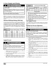
This furnace is approved for venting with Schedule 40 PVC,
CPVC, ABS, Cellular Core pipe fittings and SDR-26 PVC.
NOTE: All PVC, CPVC, ABS, and Cellular Core pipe fittings, sol-
vent cement, primers and procedures MUST conform to Ameri-
can National Standard Institute and American Society for Testing
and Materials (ANSI/ASTM) standards.
Pipe and Fittings - ASTM D1785, D2241, D2466, D2661,
D2665, F-891, F-628
• PVC Primer and 5olvent Cement- ASTM D2564
• Procedure for Cementing Joints - Ref ASTM D2855
NOTE: In order to create a seal that allows future removal of pipe,
RTV sealant MUST be used on the inlet pipe where itjoins to
the furnace. PVC, CPVC, ABS, and Cellular Core pipe and ce-
ment may be used on all other joints.
CAUTION
Do NOT use solvent cement that has become curdled, lumpy
or thickened and do NOT thin. Observe precautions printed
on containers. For applications below 32 ° F., use only low
temperature type solvent cement.
1. Cut pipe end square, remove ragged edges and burrs.
Chamfer end of pipe, then clean fitting, socket and pipe
joint of all dirt, grease, or moisture.
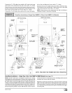
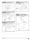
Install all couplings, nipples and elbows using proper pro-
cedures for Joining Pipe and Fittings and maintain spac-
ing between vent and combustion air piping as indicated in
Figure 19 through Figure 27.
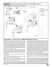
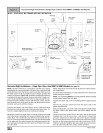
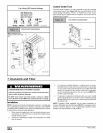
Sidewall Termination 12" or More
Above Snow Level or Grade Level
MIN. _18" Minimum for cold climates
(substained below 0° F)
Horizontal Termination
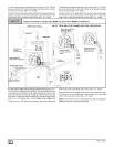
1 , 1 ,
Cuttwoholes. 2 /2' for 2"pipe, 3" for 2 /2' pipe, or3 /2' for
3" pipe. Do NOT make the holes oversized, or itwill be nec-
essary to add a sheet metal or plywood plate on the outside
with the correct size hole in it.
44001 111400 I_