


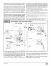
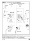
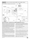
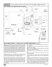
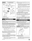
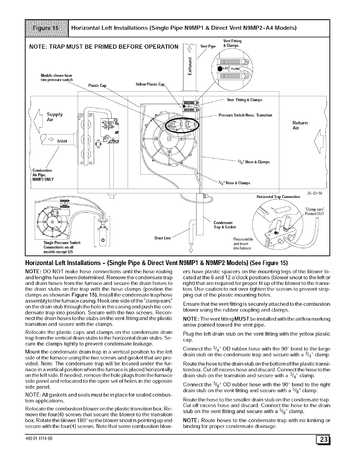
Horizontal Left Installations (Single Pipe N9MP1 & Direct Vent N9MP2-A4 Models)
NOTE: TRAP MUST BE PRIMED BEFORE OPERATION
Models shown have
two pressure switch
_._lastic Cap
Supply _
Air ,_
2_
_> Inlet
/
Combustion
AirPipe,
N9MP2ONLY
VentFitting
tPipe &Clamps
VentFitting&Clamps
Transition
518" Hose & Clamps
"Hose &Clamps
Return
Air
)Connection
25-23-58
Condensate
Trap & Gasket
"Clamp ears"
, Pointed OUT
Drain Line
Single Pressure Switch and insert
Connections on all _L, into furnace
models except 125
V
Horizontal Left Installations - (Single Pipe & Direct Vent N9MP1 & N9MP2 Models) (See Figure 15)
NOTE: DO NOT make hose connections until the hose routing
and lengths have been determined. Remove the condensate trap
and drain hoses from the furnace and secure the drain hoses to
the drain stubs on the trap with the hose clamps (position the
clamps as shown in Figure 15). Install the condensate trap/hose
assembly to the furnace casing. Hook one side of the "clamp ears"
on the drain stub through the hole in the casing and push the con-
densate trap into position. Secure with the two screws. Recon-
nect the drain hoses to the stubs on the vent fitting and the plastic
transition and secure with the clamps.
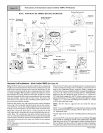
Relocate the plastic caps and clamps on the condensate drain
trap from the vertical drain stubs to the horizontal drain stubs. Se-
cure the clamps tightly to prevent condensate leakage.
Mount the condensate drain trap in a vertical position to the left
side of the furnace using the two screws and gasket that are pro-
vided. Note: The condensate trap will be located under the fur-
nace in a vertical position when the furnace is placed horizontally
on the left side. If needed, remove the hole plugs from the furnace
side panel and relocated to the open set of holes in the opposite
side panel.
NOTE: All gaskets and seals must be in place for sealed combus-
tion applications.
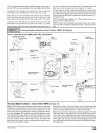
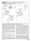
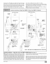
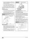
Relocate the combustion blower on the plastic transition box. Re-
move the four(4) screws that secure the blower to the transition
box. Rotate the blower 180 ° so the blower snout is pointing up and
secure with the four(4) screws. Note that some combustion blow-
ers have plastic spacers on the mounting legs of the blower lo-
cated at the 6 and 12 o'clock positions (blower snout to the left or
right) that are required for proper fit up of the blower to the transi-
tion. Use caution to not over tighten the screws to prevent strip-
ping out of the plastic mounting holes.
Ensure that the vent fitting is securely attached to the combustion
blower using the rubber coupling and clamps.
NOTE: The vent fitting MUST be installed with the airflow marking
arrow pointed toward the vent pipe.
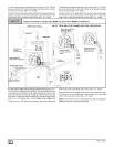
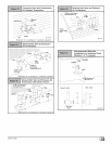
Plug the left drain stub on the vent fitting with the yellow plastic
cap.
Connect the 3/4" OD rubber hose with the 90 ° bend to the large
3 ,
drain stub on the condensate trap and secure with a /4' clamp.
Route the hose to the drain stub on the bottom of the plastic transi-
tion box. Cut off excess hose and discard. Connect the hose tothe
drain stub on the transition and secure with a 3/4" clamp.
Connect the 518" OD rubber hose with the 90 ° bend to the right
drain stub on the vent fitting and secure with a 518"clamp.
Route the hose to the smaller drain stub on the condensate trap.
Cut off excess hose and discard. Connect the hose to the drain
stub on the vent fitting and secure with a 5/8" clamp,
NOTE: Route hoses to the condensate trap with no kinking or
binding for proper condensate drainage.
44001 111400 [_