CARBON MONOXIDE POISONING HAZARD
This could result in death, personal injury and/or
property damage.
Cool air passing over heat exchanger can cause
condensate to form resulting in heat exchanger failure.
Connections
NOTE: On upflow installations, return air can enter through either
side, both sides, orthe bottom. On horizontal or downflowinstalla-
tions the return air must enter through the knockout opening in the
lower panel of the furnace. Return air can not enter through rear
of the furnace. When the furnace is located in an area near or ad-
jacent to the living area, the system should be carefully designed
with returns to minimize noise transmission through the return
grille. Any blower moving a high volume of air will produce audible
noise which could be objectionable to when the unit is located
very close to living areas. It is advisable to route the return air
ducts under the floor or through the attic.
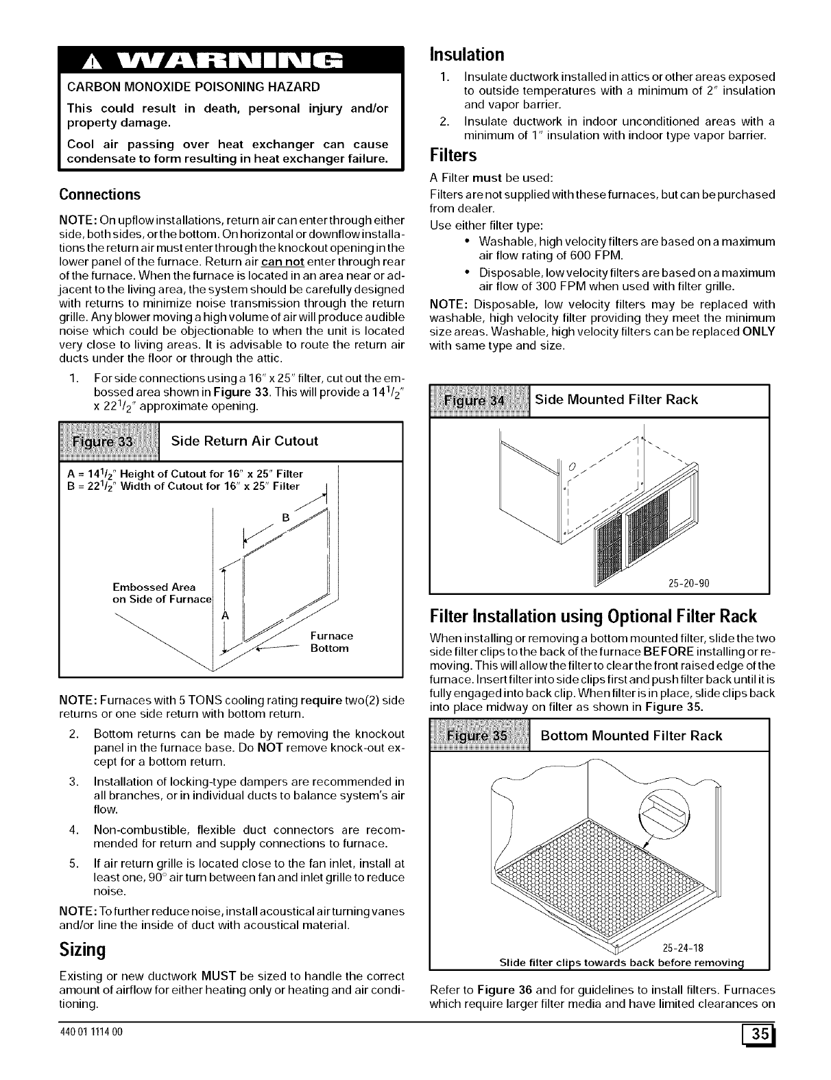
1. Forsideconnectionsusinga16"x25"filter, cutouttheem-
bossed area shown in Figure 33. This will provide a 141/2"
x 221/2" approximate opening.
i;[ :;; [
Side Return Air C UtO Ut
iiiiiiiiiiiiiiiiiiiiiiiiiiiiiiiiiiiiiiiiiiiiiiiiiiiiiiiiiiiiiiiiiiiiiiiiiiiiiiiiiiiiiiiiiiiiiiiiiiiiiiiiiiiiiiiiiiiiiiiiiiii
Height of Cutout for 16" x 25" Filter
AB==221/z"141/z"Width of Cutout for 16" x 25" Filter/_
Embossed Area _jmC e
on Side of Furnace
NOTE: Furnaces with 5 TONS cooling rating require two(2) side
returns or one side return with bottom return.
2. Bottom returns can be made by removing the knockout
panel in the furnace base. Do NOT remove knock-out ex-
cept for a bottom return.
3. Installation of locking-type dampers are recommended in
all branches, or in individual ducts to balance system's air
flow.
4. Non-combustible, flexible duct connectors are recom-
mended for return and supply connections to furnace.
5. If air return grille is located close to the fan inlet, install at
least one, 90 ° air turn between fan and inlet grille to reduce
noise.
NOTE: To further reduce noise, install acoustical air turning vanes
and/or line the inside of duct with acoustical material.
Sizing
Existing or new ductwork MUST be sized to handle the correct
amount of airflow for either heating only or heating and air condi-
tioning.
44001 111400
Insulation
1. Insulate ductwork installed in attics or other areas exposed
to outside temperatures with a minimum of 2" insulation
and vapor barrier.
2. Insulate ductwork in indoor unconditioned areas with a
minimum of 1" insulation with indoor type vapor barrier.
Filters
A Filter must be used:
Filters are not supplied with these furnaces, but can be purchased
from dealer.
Use either filter type:
• Washable, high velocity filters are based on a maximum
air flow rating of 600 FPM.
• Disposable, low velocity filters are based on a maximum
air flow of 300 FPM when used with filter grille.
NOTE: Disposable, low velocity filters may be replaced with
washable, high velocity filter providing they meet the minimum
size areas. Washable, high velocity filters can be replaced ONLY
with same type and size.
Side Mounted Filter Rack
25-20-90
Filter Installation using Optional Filter Rack
When installing or removing a bottom mounted filter, slide the two
side filter clips to the back of the furnace BEFORE installing or re-
moving. This will allow the filter to clear the front raised edge of the
furnace. Insert filter into side clips first and push filter back until it is
fully engaged into back clip. When filter is in place, slide clips back
into place midway on filter as shown in Figure 35.
Bottom Mounted Filter Rack
25-24-18
Slide filter clips towards back before removin_l
Refer to Figure 36 and for guidelines to install filters. Furnaces
which require larger filter media and have limited clearances on


