


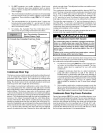
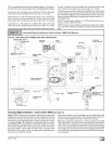
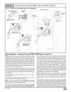
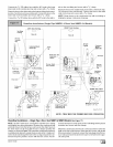

Upflow Installations (Single Pipe N9MP1 & Direct Vent N91VIP2-A4 Models)
NOTE: TRAP MUST BE PRIMED BEFORE OPERATION
DRAIN SIDE VIEW VentFitting
/,/_a te & Clampsdownward
NOTE_. Built-in channel will
be angled 5° to 10° also.
Single Pressure Switch
Connections on all
models except 125
LEFT Side Venting
PVC Vent
Extension Pipe
dwg 25-24-06
Trap Connection
lamp ears '_
inted OUT
Preassemble & insert
into furnace
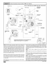
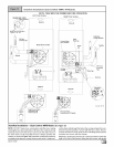
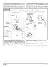
Upflow Installations - (Single Pipe & Direct Vent N9MP1
NOTE: DO NOT make hose connections until the hose routing
and lengths have been determined. Remove the condensate trap
and drain hoses from the furnace and secure the drain hoses to
the drain stubs on the trap with the hose clamps (position the
clamps as shown in Figure 13). Install the condensate trap/hose
assembly to the furnace casing. Hook one side ofthe"cla mp ears"
on the drain stub through the hole in the casing and push the con-
densate trap into position. Secure with the two screws. Recon-
nect the drain hoses to the stubs on the vent fitting and the plastic
transition and secure with the clamps.
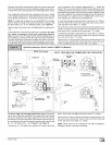
Mount the condensate drain trap in a vertical position to either the
left or right side of the furnace using the two screws and gasket
that are provided. If needed, remove the hole plugs from the fur-
nace side panel and relocate to the open set of holes in the oppo-
site side panel.
NOTE: All gaskets and seals must be in place for sealed combus-
tion applications.
Ensure that the vent fitting is securely attached to the combustion
blower using the rubber coupling and clamps.
NOTE: For left side venting, the vent fitting MUST be installed
with the airflow marking arrow pointed toward the vent pipe, with
the drain stub at a 5° to 10 ° downward slope.
Connect the PVC vent extension pipe to the vent fitting. This pipe
has a built-in channel to assist vent condensate disposal.
Align the arrow on the PVC pipe with the airflow marking arrow on
44001 111400
& N9MP2 Models) (See Figure13)
the vent fitting. See label on the PVC pipe for proper installation.
This pipe may only be shortened if an elbow is used to connect the
PVC vent extension tube to field-installed vent pipe. Securely at-
tach the PVC vent extension pipe to the vent fitting with the cla rap.
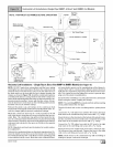
This configuration allows left side venting from the furnace. If right
side venting isrequired, the combustion blower must be relocated
on the plastic transition box. Loosen the four(4) screws that se-
1 ,
cure the blower to the transition approximately /2'. Rotate the
blower 180 ° and secure with the four(4) screws. Note that some
combustion blowers have plastic spacers on the mounting legs of
the blower located at the 6 and 12 o'clock positions (blower snout
to the left or right) that are required for proper fit up of the blower to
the transition. Use caution to not over tighten the screws to pre-
vent stripping out of the plastic mounting holes.
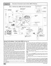
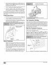
NOTE: For right side venting, the vent fitting MUST be installed
with the airflow marking arrow pointed toward the vent pipe, with
the drain stub at a 5° to 10 ° downward slope. (See Figure 14)
Plug the upper drain stub on the vent fitting with the yellow plastic
cap.
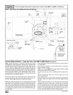
Connect the PVC vent extension pipe to the vent fitting. This pipe
has a built-in channel to assist vent condensate disposal.
Align the arrow on the PVC pipe with the airflow marking arrow on
the vent fitting. See label on the PVC pipe for proper installation.
This pipe may only be shortened if an elbow is used to connect the
PVC vent extension tube to field-installed vent pipe. Securely at-
tach the PVC vent extension pipe to the vent fitting with the cla rap.