


3. Installairintakeaminimumof12"abovemaximumsnow
levelandclearofanyobstruction.Ductorventilationopen-
ingrequiresonesquareinchoffreeareaper4,000BTUH
oftotal input rating for all gas appliances in area.
4. Air inlet MUST be screened with not less than 1/4" mesh
screen.
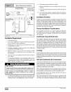
Unusually Tight Construction
In unconfined spaces, infiltration may be adequate to provide air
for combustion, ventilation and dilution of flue gases. However, in
buildings with unusually tight construction, additional air MUST
be provided using the methods described in section titled Con-
fined Space Installation:
Unusually tight construction is defined as: Construction with
1. Walls and ceilings exposed to the outside have a continu-
ous, sealed vapor barrier. Openings are gasketed or
sealed and
2,
3.
Doors and openable windows are weather stripped and
Other openings are caulked or sealed. These include joints
around window and door frames, between sole plates and
floors, between wall-ceiling joints, between wall panels, at
penetrations for plumbing, electrical and gas lines, etc.
Ventilation Air
Some provincial codes and local municipalities require ventilation
or make-up air be brought into the conditioned space as replace-
ment air. Whichever method is used, the mixed return air temper-
ature across the heat exchanger MUST not fall below 60 °F or flue
gases will condense in the heat exchanger. This will shorten the
life of the heat exchanger and possibly void your warranty.
Venting and Combustion Air Check
The following information is supplied to allow the installer to make
adjustments to the setup of existing appliances, IF REQUIRED,
based on good trade practices, local codes, and good judgement
of the installer. Manufacturer does NOT take responsibility for
modifications made to existing equipment.
NOTE: If this installation replaces an existing furnace from a
commonly vented system, the original venting system may no
longer be sized to properly vent the attached appliances. An im-
properly sized venting system may cause the formation of con-
densate in the vent and the leakage or spillage of vent gases. To
make sure there is adequate combustion air for all appliances,
MAKE THE FOLLOWING CHECK.
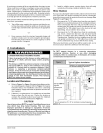
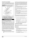
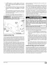
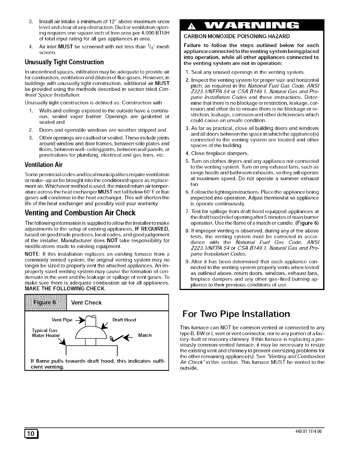
Vent Check
VentPipe --_1 [ A/ Draft Hood
Typical Gas
Water Heater,_ f [ [ _ _,_._. Match
I
!
If flame pulls towards draft hood, this indicates suffi-
cient venting.
CARBON MONOXIDE POISONING HAZARD
Failure to follow the steps outlined below for each
appliance connected to the venting system being placed
into operation, while all other appliances connected to
the venting system are not in operation:
1. Seal any unused openings in the venting system.
2. Inspect the venting system for proper size and horizontal
pitch, as required in the National Fuel Gas Code, ANSI
Z223,1/NFPA 54 or CSA B149. 1, Natural Gas and Pro-
pane Installation Codes and these instructions. Deter-
mine that there is no blockage or restriction, leakage, cor-
rosion and other de to ensure there is no blockage or re-
striction, leakage, corrosion and other deficiencies which
could cause an unsafe condition.
3. As far as practical, close all building doors and windows
and all doors between the space in which the appliance(s)
connected to the venting system are located and other
spaces of the building.
4. Close fireplace dampers.
5. Turn on clothes dryers and any appliance not connected
to the venting system. Turn on any exhaust fans, such as
range hoods and bathroom exhausts, so they will operate
at maximum speed. Do not operate a summer exhaust
fan.
6. Followthe lighting instructions. Place the appliance being
inspected into operation. Adjust thermostat so appliance
is operate continuously.
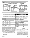
7. Test for spillage from draft hood equipped appliances at
the draft hood relief opening after 5 minutes of main burner
operation. Use the flame of a match or candle. (Figure 6)
8. If improper venting is observed, during any of the above
tests, the venting system must be corrected in accor-
dance with the National Fuel Gas Code, ANSI
Z223,1/NFPA 54 or CSA B149. 1, Natural Gas and Pro-
pane Installation Codes.
9. After it has been determined that each appliance con-
nected to the venting system properly vents when tested
as outlined above, return doors, windows, exhaust fans,
fireplace dampers and any other gas-fired burning ap-
pliance to their previous conditions of use.
For Two Pipe Installation
This furnace can NOT be common vented or connected to any
type B, BW or L vent or vent connector, nor to any portion of a fac-
tory-built or masonry chimney. If this furnace is replacing a pre-
viously common-vented furnace, it may be necessary to resize
the existing vent and chimney to prevent oversizing problems for
the other remaining appliance(s). See "Venting and Combustion
Air Check"in this section. This furnace MUST be vented to the
outside.
E_ 44001 111400