


iiiiM!!iMiIiii_iIiiiiiiiiIiiii(iii?iiiiiii:i;;ijIiiiiiHii![iiii_iii(iiiji_ii_ifiii_;ii!i!!!i}[_iiii_i;iiii
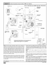
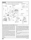
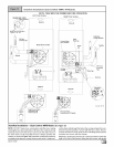
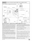
Downflow Installations (Dual Certified *9MPD-A4 Models)
iiiiiiiiiiiiiiiiiiiiiiiiiiiiiiiiiiiiiiiiiiiiiiiiiiiiiiiiiiiiiiiiiiiiiiiiiiiiiiiiiiiiiiiiiiiiiiiiiiiiiiiiiiiiiiiiiiiiiiii
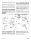
NOTE: TRAP MUST BE PRIMED BEFORE OPERATION
DRAIN SIDE VIEW LEFT Side VentJn_ RIGHT Side Venting
_tate downward @
/ 5° to 10° v
/ ReturnAir ReturnAir
NOTE'_ Bddt-in channel _ll be
angled 5° to 10° also.
Combustion
_4_ AirPipe,(Optional)
PVC Vent Yellow /
Extenst?n Ptpe Pressure Switch Plastic Cap _ /
-_ / Hose,Transition / _ /
n LU / (Rotate180°for LeftSide) \ / / VentPine
P L _ \ _ Plastic / -7 r
_>- _ _ \ \ Cap _/ _ /
3/4" Hose _ _ _ \ Pipe
1 &Clamps _8" H°se_ \ Plastic Caps
\
S.pp,, X
_LJ Single Pressure Switch {F}L_
Connections()nail /l_/" 2PressureSwitch
models except 125
moaetsexcepltza _ Connectiononall125models
© o
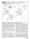
Downflow Installations - (Dual Certified *9MPD Models) (See Figure 12)
NOTE: DO NOT make hose connections until the hose routing
and lengths have been determined. Remove the condensate trap
and drain hoses from the furnace and secure the drain hoses to
the drain stubs on the trap with the hose clamps (position the
clamps as shown in Figure 12). Install the condensate trap/hose
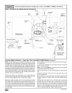
assemblyto the furnace casing. Hook one side ofthe"cla mp ears"
44001 111400
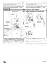
on the drain stub through the hole in the casing and push the con-
densate trap into position. Secure with the two screws. Recon-
nect the drain hoses to the stubs on the vent fitting and the plastic
transition and secure with the clamps.
Mount the condensate drain trap in a vertical position to either the
right or left side of the furnace using the two screws and gasket