


3. DoNOTterminate over public walkways. Avoid areas
where condensate may cause problems such as above
planters, patios, or adjacent to windows where steam may
cause fogging.
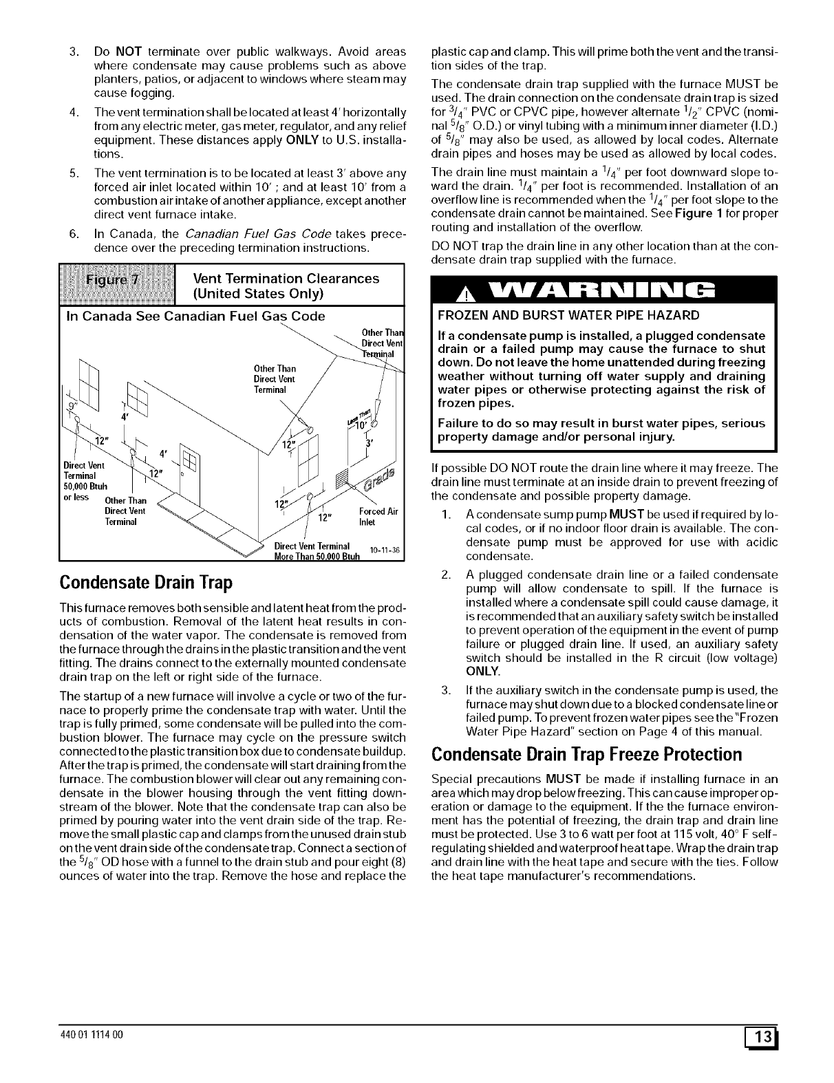
4. The vent termination shall be located at least 4' horizontally
from any electric meter, gas meter, regulator, and any relief
equipment. These distances apply ONLY to U.S. installa-
tions.
The vent termination is to be located at least 3' above any
forced air inlet located within 10' ; and at least 10' from a
combustion air intake of another appliance, except another
direct vent furnace intake.
In Canada, the Canadian Fuel Gas Code takes prece-
dence over the preceding termination instructions.
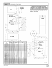
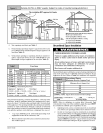
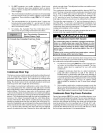
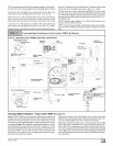
Vent Termination Clearances
(United States Only)
In Canada See Canadian Fuel Gas Code
OtherThan
OtherThan
DirectVent
Terminal
\
Condensate Drain Trap
This furnace removes both sensible and latent heat from the prod-
ucts of combustion. Removal of the latent heat results in con-
densation of the water vapor. The condensate is removed from
the furnace through the drains in the plastic transition and the vent
fitting. The drains connect to the externally mounted condensate
drain trap on the left or right side of the furnace.
The startup of a new furnace will involve a cycle or two of the fur-
nace to properly prime the condensate trap with water. Until the
trap is fully primed, some condensate will be pulled into the com-
bustion blower. The furnace may cycle on the pressure switch
connected to the plastic transition box due to condensate buildup.
After the trap is primed, the condensate will start draining from the
furnace. The combustion blower will clear out any remaining con-
densate in the blower housing through the vent fitting down-
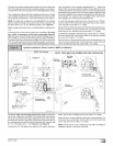
stream of the blower. Note that the condensate trap can also be
primed by pouring water into the vent drain side of the trap. Re-
move the small plastic cap and clamps from the unused drain stu b
on the vent drain side of the condensate trap. Connect a section of
the 518"OD hose with a funnel to the drain stub and pour eight (8)
ounces of water into the trap. Remove the hose and replace the
plastic cap and clamp. This will prime both the vent and the transi-
tion sides of the trap.
The condensate drain trap supplied with the furnace MUST be
used. The drain connection on the condensate drain trap is sized
for 3/4" PVC or CPVC pipe, however alternate 1/2" CPVC (nomi-
nal 5/8" O.D.) or vinyl tubing with a minimum inner diameter (I.D.)
of 5/8" may also be used, as allowed by local codes. Alternate
drain pipes and hoses may be used as allowed by local codes.
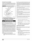
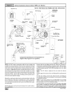
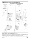
The drain line must maintain a 1/4" per foot downward slope to-
ward the drain. 1/4" per foot is recommended. Installation of an
overflow line is recommended when the 1/4" per foot slope to the
condensate drain cannot be maintained. See Figure 1 for proper
routing and installation of the overflow.
DO NOT trap the drain line in any other location than at the con-
densate drain trap supplied with the furnace.
FROZEN AND BURST WATER PIPE HAZARD
If a condensate pump is installed, a plugged condensate
drain or a failed pump may cause the furnace to shut
down. Do not leave the home unattended during freezing
weather without turning off water supply and draining
water pipes or otherwise protecting against the risk of
frozen pipes.
Failure to do so may result in burst water pipes, serious
property damage and/or personal injury.
If possible DO NOT route the drain line where it may freeze. The
drain line must terminate at an inside drain to prevent freezing of
the condensate and possible property damage.
1. A condensate sump pump MUST be used if required by lo-
cal codes, or if no indoor floor drain is available. The con-
densate pump must be approved for use with acidic
condensate.
A plugged condensate drain line or a failed condensate
pump will allow condensate to spill. If the furnace is
installed where a condensate spill could cause damage, it
is recommended that an auxiliary safety switch be installed
to prevent operation of the equipment in the event of pump
failure or plugged drain line. If used, an auxiliary safety
switch should be installed in the R circuit (low voltage)
ONLY.
3. If the auxiliary switch in the condensate pump is used, the
furnace may shut down due to a blocked condensate line or
failed pump. To prevent frozen water pipes see the "Frozen
Water Pipe Hazard" section on Page 4 of this manual.
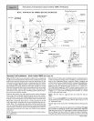
Condensate Drain Trap Freeze Protection
Special precautions MUST be made if installing furnace in an
area which may drop below freezing. This can cause improper op-
eration or damage to the equipment. If the the furnace environ-
ment has the potential of freezing, the drain trap and drain line
must be protected. Use 3 to 6 watt per foot at 115 volt, 40 ° F self-
regulating shielded and waterproof heat tape. Wrap the drain trap
and drain line with the heat tape and secure with the ties. Follow
the heat tape manufacturer's recommendations.
44001 111400 [_