


Thispipemayonlybeshortenedifanelbowisusedtoconnectthe
PVCventextensiontubetofield-installedventpipe.Securelyat-
tachthePVCventextensionpipetotheventfittingwiththeclarap.
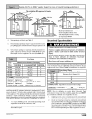
Thisconfigurationallowsleftsideventingfromthefurnace.Ifright
sideventingisrequired,thecombustionblowermustberelocated
ontheplastictransitionbox.Loosenthefour(4)screwsthatse-
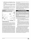
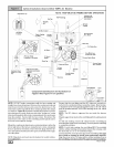
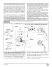
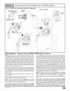
NOTE:Forrightsideventing,theventfittingMUSTbeinstalled
withtheairflowmarkingarrowpointedtowardtheventpipe,with
thedrainstubata5°to10°downwardslope.(SeeFigure9)
Plug the upper drain stub on the vent fitting with the yellow plastic
cap.
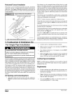
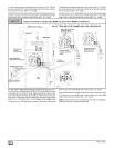
Connect the PVC vent extension pipe to the vent fitting. This pipe
has a built-in channel to assist vent condensate disposal.
Align the arrow on the PVC pipe with the airflow marking arrow on
the vent fitting. See label on the PVC pipe for proper installation.
This pipe may only be shortened if an elbow is used to connect the
PVC vent extension tube to field-installed vent pipe. Securely at-
tach the PVC vent extension pipe to the vent fitting with the cla rap.
up.ow,nsta.a.ons(Dua,Cer..ed"gMPD-A4Mode,s)
iiiiiiiiiiiiiiiiiiiiiiiiiiiiiiiiiiiiiiiiiiiiiiiiiiiiiiiiiiiiiiiiiiiiiiiiiiiiiiiiiiiiiiiiiiiiiiiiiiiiiiiiiiiiiiiiiiiiiiii
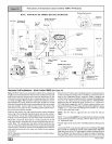
RIGHT Side Venting
Supply Air
Trap Connection
"Clampears"
ointedOUT •
eassemble
dinsert
MountingScrews(4)
forRotatingCombustion _
Blower _
DRAIN SIDE VIEW _
_ Rotate downward
5° to10°
Vent
Drain
cure the blower to the transition approximately 112". Rotate the
blower 180 ° and secure with the four(4) screws. Note that some
combustion blowers have plastic spacers on the mounting legs of
the blower located at the 6 and 12 o'clock positions (blower snout
to the left or right) that are required for proper fit up of the blower to
the transition. Use caution to not over tighten the screws to pre-
vent stripping out of the plastic mounting holes.
For left side mounted condensate trap, connect the 3/4" OU rub-
ber hose with the 90 ° bend to the large drain stub on the conden-
sate trap and secure with a 3/4" clamp.
Route the hose to the drain stub on the bottom of the plastic transi-
tion box. Cut off excess hose and discard. Connect the hose to the
drain stub on the transition and secure with a 3/4" clamp.
For right side mounted condensate trap, connect the 3/4" OD rub-
ber hose with the 90 ° bend to the bottom of the plastic transition
box and secure with a 3/4" clamp.
Route the hose to the large drain stub on the condensate trap. Cut
off excess hose and discard. Connect the hose to the drain stub
on the condensate trap and secure with a 3/4" clamp.
J
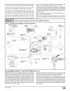
NOTE!"Fuilt-inchannelwillbe
angled 5°to10° also.
"_ Optional on
/ somemodels
c .._
__ _ PVC Vent
) ) / Extension Pipe _ _ c
25-24-05
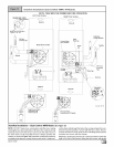
onepressureswitch
NOTE: TRAP MUST BE PRIMED BEFORE OPERATION
c
2Pressure Switch
Connectionon 125models
©
For left or right side mounted condensate trap, the pressure
tap on the condensate trap MUST be connected to the unused
pressure tap located on the upper right hand corner of the plastic
transition box. Remove the plastic caps from the pressure taps on
the condensate trap and the plastic transition and connect with
the 5/16" OD rubber hose. (See Figure 8 and Figure 9)
Connect the 5/8" OD rubber hose with the 90 ° bend to the lower
drain stub on the vent fitting and secure with a 5/8" clamp.
Route the hose to the small drain stub on the condensate trap. Cut
off excess hose and discard. Connect the hose to the drain stub
on the trap and secure with a 5/8" clamp.
NOTE: Route hoses to the condensate trap with no kinking or
binding for proper condensate drainage.
44001 111400 [_