


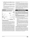
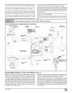
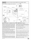
PVCventextensiontubetofield-installedventpipe.Securelyat-
tachthePVCventextensionpipetotheventfittingwiththeclarap.
Connectthe 5/8" OD rubber hose with the 90 ° bend to the lower
drain stub on the vent fitting and secure with a 5/8" clamp.
Route the hose to the horizontal drain stub on the condensate
trap. Cut off excess hoses and discard. Connect the hose to the
drain stub on the condensate trap and secure with a 5/8" clamp.
Connect the 3/4" OD rubber hose with the 90 ° bend to the large
drain stub on the condensate trap and secure with a 3/4" clamp.
Route the hose to the drain stub on the bottom of the plastic transi-
tion box. Cut off excess hose and discard. Connect the hose tothe
drain stub on the transition and secure with a 3/4" clamp.
The pressure tap on the condensate trap MUST be connected to
the unused pressure tap located on the top of the plastic transition
box. Remove the plastic caps from the pressure taps on the con-
densate trap and the plastic transition and connect with the 5/16"
OD rubber hose.
NOTE: This will require drilling a 5/16" OD hole in the furnace cas-
ing next to the condensate trap.
NOTE: Ensure hoses maintain a downward slope to the conden-
sate trap with no kinking or binding for proper condensate drain-
age.
i i
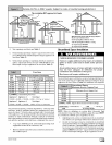
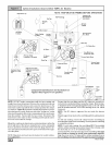
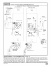
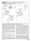
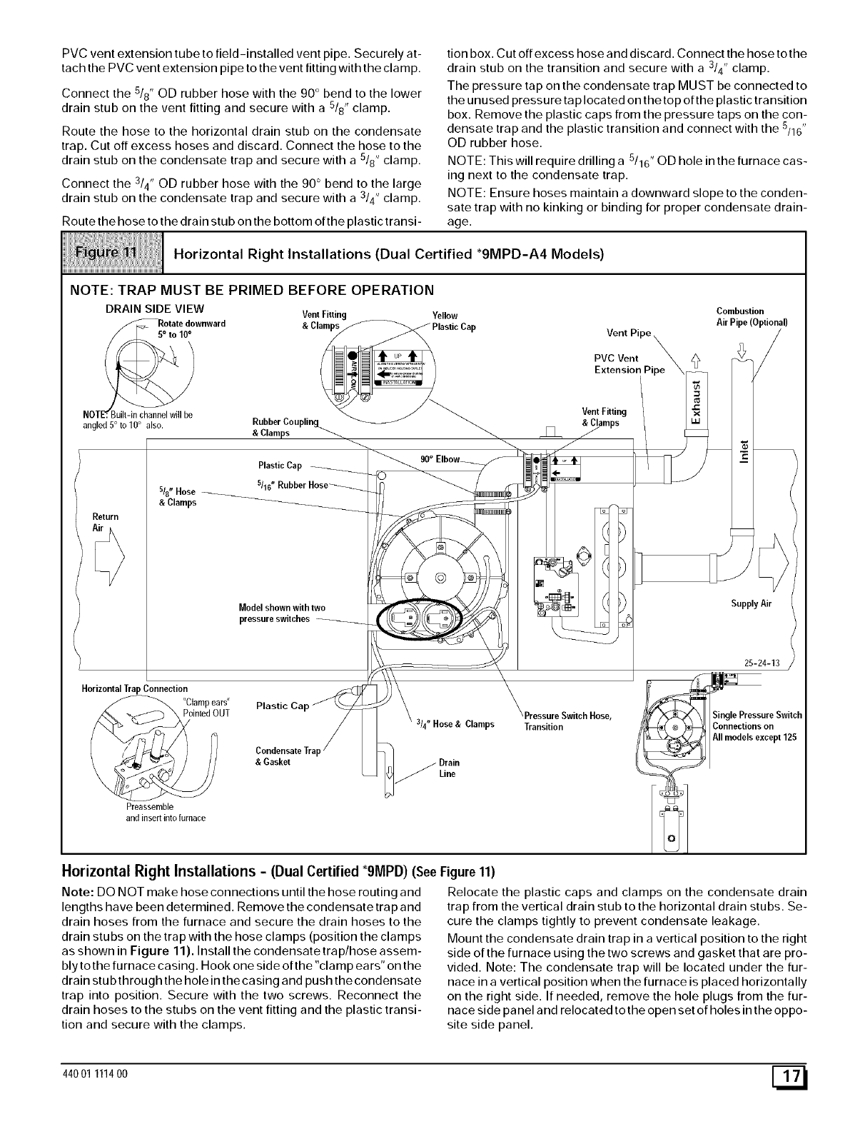
Horizontal Right Installations (Dual Certified *9MPD-A4 Models)
iiiiiiiiiiiiiiiiiiiiiiiiiiiiiiiiiiiiiiiiiiiiiiiiiiiiiiiiiiiiiiiiiiiiiiiiiiiiiiiiiiiiiiiiiiiiiiiiiiiiiiiiiiiiiiiiiiii
NOTE: TRAP MUST BE PRIMED BEFORE OPERATION
DRAIN SIDE VIEW Vent Fitting Yellow Coml_ustion.
Y "sot:W:w"ward C'aop ..astic Cap Von.Pip°__ A.r..pe<ept.oT.
/ _ / /__ PVCVent _. h_ _ /
_,_ "/ _ _ Extension Pipe \__ /
NOT .JBu_be _' /_ Vent Fitting /
angled5o toiOO also. &Ruc__:pCso upling.........._ _ _ _ /&C/lamps\ _ "_
/
Model shown withtwo _/_ _, _ _ Supply Air I
Hor,zonta.TrapConne.ion '.
"Clamp ears" Plastic Cap//_..__J \ \ '_
X_ --_ \ Po,n_eaOUT /7_ \ _e.spre SwitchHose. _ ;X3L/\ Si.g.ePre...reSwitch
/_ _-_ / ' s14" Hose &Clamps Transition / _ _ _-- Connections on
/ _/°7// _ / _, " ............ /_ AII models except125
[ I/J_ _ I )/ Condensate Trap / _ /I _ ))
\ J_-&j "_/) / /J & Gasket / Drain [/
and insert into furnace
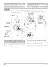
Horizontal Right Installations - (Dual Certified *9MPD) (See Figure 11)
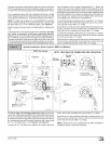
Note: DO NOT make hose connections until the hose routing and
lengths have been determined. Remove the condensate trap and
drain hoses from the furnace and secure the drain hoses to the
drain stubs on the trap with the hose clamps (position the clamps
as shown in Figure 11). Install the condensate trap/hose assem-
bly tothe furnace casing. Hook one side ofthe"clamp ears" on the
drain stub through the hole in the casing and push the condensate
trap into position. Secure with the two screws. Reconnect the
drain hoses to the stubs on the vent fitting and the plastic transi-
tion and secure with the clamps.
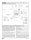
Relocate the plastic caps and clamps on the condensate drain
trap from the vertical drain stub to the horizontal drain stubs. Se-
cure the clamps tightly to prevent condensate leakage.
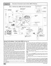
Mount the condensate drain trap in a vertical position to the right
side of the furnace using the two screws and gasket that are pro-
vided. Note: The condensate trap will be located under the fur-
nace in a vertical position when the furnace is placed horizontally
on the right side. If needed, remove the hole plugs from the fur-
nace side panel and relocated to the open set of holes in the oppo-
site side panel.
44001 111400 [_