


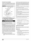
4. Vent and Combustion Air Piping
CARBON MONOXIDE POISONING, FIRE AND EXPLO-
SION HAZARD
Failure to properly vent this furnace can result in death,
personal injury and/or property damage.
Read and follow all instructions in this section.
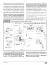
Single Pipe (N9MP1Models)
This furnace is certified as a category IV appliance. This furnace
requires ventilation openings to provide air for proper combustion
and ventilation of flue gases. All duct or openings for supplying
combustion and ventilation air must comply with the gas codes or
in absence of local codes, the applicable national codes.
When the installation is complete, see the "Venting and Com-
bustion Air Checl4' in this manual.
Direct Vent (N9MP2 Models)
This furnace is certified as a category ]V appliance. This furnace
uses outside air for combustion ONLY, it MUST be taken from the
same atmospheric pressure zone as the vent pipe. See Con-
fined Space Installation in the Combustion and Ventilation
Air in this manual.
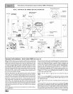
Dual Certified ('gMPD Models)
This furnace is certified as a category ]V appliance. This furnace
can be installed as a direct vent furnace using outside air for com-
bustion or the furnace can use air from inside the structure for
combustion. The INLET air pipe is optional. If combustion air
comes from inside the structure, adequate make up air MUST be
provided to compensate for oxygen burned. See Confined
Space Installation in the Combustion and Ventilation Air
chapter. If combustion air is drawn from outside the structure, it
MUST be taken from the same atmospheric pressure zone as the
vent pipe.
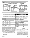
Contaminated Combustion Air
Installations in certain areas or types of structures will increase
the exposure to chemicals or halogens that may harm the fur-
Race.
The following areas or types of structures may contain or have ex-
posure to the substances listed below. The installation must be
evaluated carefully as it may be necessary to provide outside air
for combustion.
• Commercial buildings.
• Buildings with indoor pools.
• Furnaces installed in laundry rooms.
• Furnaces installed in hobby or craft rooms.
• Furnaces installed near chemical storage areas.
• Permanent wave solutions for hair.
• Chlorinated waxes and cleaners.
• Chlorine based swimming pool chemicals.
• Water softening chemicals.
• De-icing salts or chemicals.
• Carbon tetrachloride.
• Halogen type refrigerants.
• Cleaning solvents (such as perchloroethylene).
44001 111400
• Printing inks, paint removers, varnishes, etc.
• Hydrochloric acid.
• Sulfuric Acid.
• Solvent cements and glues.
• Antistatic fabric softeners for clothes dryers.
• Masonry acid washing materials.
Vent and Combustion Air Piping Guidelines
This furnace is approved for venting with Schedule 40 PVC,
CPVC, ABS, Cellular Core pipe fittings and SDR-26 PVC.
NOTE: All PVC, CPVC, ABS, and Cellular Core pipe fittings, sol-
vent cement, primers and procedures MUST conform to Ameri-
can National Standard Institute and American Society for Testing
and Materials (ANSI/ASTM) standards.
• Pipe and Fittings - ASTM D1785, D2241, D2466, D2661,
D2665, F-891, F-628
• PVC Primer and Solvent Cement- ASTM D2564
• Procedure for Cementing Joints - Ref ASTM D2855
NOTE: All vent piping MUST be installed in compliance with local
codes or ordinances, these instructions, good trade practices,
and codes of country having jurisdiction.
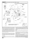
1. Determine the best routing and termination for the vent
pipe and air inlet pipe by referring to all of the instructions
and guidelines in this Section.
2. Determine the size required for the vent pipe and air inlet
pipe.
3. Loosely assemble all venting parts without adhesive (pipe
joint cement) for correct fit before final assembly.
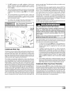
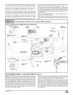
4. Use of vertical piping is preferred because there will be
some moisture in the flue gases that may condense as it
leaves the vent pipe (See Special Instruction For Horizon-
tal Vents).
5. The vertical vent pipe MUST be supported so that no
weight is allowed to rest on the combustion blower.
6. Exhaust vent piping or air inlet piping diameter MUST NOT
be reduced.
7. All exhaust vent piping from the furnace to termination
MUST slope upwards. A minimum of 1/4" per foot of run is
required to properly return condensate to the furnace drain
system.
8. Use DWV type long radius elbows whenever possible, as
they provide for the minimum slope on horizontal runs and
they provide less resistance in the vent system. If DWV el-
bows cannot be used, use two, 45 ° elbows when possible.
On horizontal runs the elbows can be slightly misaligned to
provide the correct slope.
9. All horizontal pipe runs MUST be supported at least every
five feet with galvanized strap or other rust resistant materi-
al. NO sags or dips are permitted.
10. All vertical pipe runs MUST be supported every six feet
where accessible.
11.
12.
The minimum pipe run length is 2'.
The piping can be run in the same chase or adjacent to sup-
ply or vent pipe for water supply or waste plumbing. Itcan
also be run inthe same chase with a vent from another 90+
furnace.
NOTE: In NO case can the piping be run in a chase where
temperatures can exceed 140 ° F. or where radiated heat
from adiacent surfaces would exceed 140 ° F.