


4. Relightallappliancesandensureallpilotsareoperating.
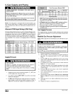
NOTE: If meter uses a 2 cubic foot dial, divide results (seconds)
by two.
Gas Piping Requirements
NOTE: The gas supply line must be installed by a qualified ser-
vice technician inaccordance with all building codes, (In the state
of Massachusetts, gas supply connections MUST be performed
by a licensed plumber or gas fitter).
1. Properly size gas pipe to handle combined appliance load
or run gas pipe directly from gas meter orLP gas regulator.
Refer to NFGC and ANSI Z223.1 for proper gas pipe size.
2. Install correct pipe size for run length and furnace rating.
3. Measure pipe length from gas meter or LP second stage
regulator.
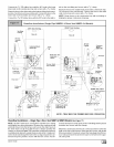
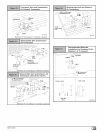
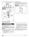
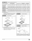
NOTE: Refer to Figure 29 or Figure 30 for the general layout at
the furnace. The rules listed apply to natural and LP gas pipe
installations.
NOTE: On the Dual Certified or Direct Vent models, install the gas
pipe grommet to the furnace side panel with the gas pipe entry. If
needed, remove the 2" hole plug and relocate to the open hole in
the furnace side panel.
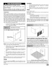
If a flexible connector is required or allowed by
authority having jurisdiction, black iron pipe shall be
installed at gas valve and extended a minimum of 2"
outside furnace casing.
4. Use black iron or steel pipe and fittings or other pipe ap-
proved by local code.
NOTE: The use of copper tubing for gas piping is NOT approved
by the state of Massachusetts.
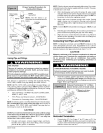
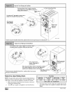
5. Use ground joint unions and install a drip leg no less than 3"
long to trap dirt and moisture before it can enter gas valve.
6. Use two pipe wrenches when making connections to pre-
vent gas valve from turning.
7. Install a manual shut-off valve external to furnace casing
and tighten all joints securely.
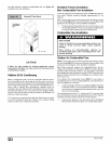
Additional LP Connection Requirements
1. Have a licensed LP gas dealer make all connections at
storage tank and check all connections from tank to fur-
Race.
2. If copper tubing is used, it MUST comply with limitation set
in National Fuel Gas Code or CGA codes.
3. Two-stage regulation of LP gas is recommended.
Final Check
1. The furnace and the gas valve must be disconnected from
the gas supply piping system during any pressure testing of
that system at test pressures in excess of 1/2" PSIG. Close
the manual shut-off valve before testing at such pressures.
2. When installation is complete, test all pipe connections for
1 ,
leaks with the gas pressure less than /2' PSIG to the gas
valve.
3. Apply a commercial soap solution to all joints to test for
leaks. Correct any leaks indicated by bubbles.
Correct even the smallest leak at once.4,
5.
Check for leaks at gas valve and orifice connections to the
burner manifold along with the pilot tube connections to the
valve and pilot assembly while the furnace is operating.
6. Electrical Wiring
ELECTRICAL SHOCK HAZARD
Failure to do so can result in death, personal inju-
ry and/or property damage.
Turn OFF electric power at fuse box or service
panel before making any electrical connections
and ensure a proper ground connection is made
before connecting line voltage.
Power SupplyWiring
The furnace MUST be electrically wired and grounded in accor-
dance with local codes, or in the absence of local codes with the
latest edition of The National Electric Code, ANSI NFPA 70 and/or
The Canadian Electric Code CSA C22.1.
Field wiring connections must be made inside the furnace con-
nection box. A suitable strain relief should be used at the point the
wires exit the furnace casing.
Copper conductors must be used. Line voltage wires should be
sized for the input amps stated on the rating plate. Furnace should
be connected to its own separate circuit.
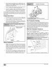
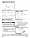
Thermostat
Thermostat location has an important effect on the operation of
the unit. Follow instructions included with thermostat for correct
mounting and wiring.
Low voltage connections to furnace must be made on terminal
board to fan control.
44001 111400
Set thermostat heat anticipator in accordance with the Technical
Support Manual.
Optional Equipment
All wiring from furnace to optional equipment MUST conform to
local codes or, in the absence of local codes with the latest edition
of The National Electric Code, ANSI NFPA 70 and/or The Cana-
dian Electric Code CSA C22.1. Install wiring in accordance with
manufacturer's instructions. The wiring MUST have a minimum
temperature rating of 105 ° C.
Humidifier/Electronic Air Cleaner
The furnace is wired for humidifier and/or electronic air cleaner
connection.
CAUTION
Do NOT exceed 115V/0.8 amp. maximum current load for
both the EAC terminal and the HUM terminal combined.
NOTE: The humidifier will be powered when the furnace is fired
and the circulating air blower comes on. The electronic air cleaner
will be powered anytime the air circulating blower is energized.
However, the electronic air cleaner is NOT energized during con-
tinuous fan operation controlled by the electronic fan control.
Fan Control
The fan control is preset at the factory with a fixed blower ON
delay of 30 seconds in the heating mode. The blower OFF timing
is preset at 140 seconds. If desired, the fan OFF delay can be re-
set to obtain the longest delay times while still maintaining comfort
levels. See "Furnace Wiring Diagram".