


Chapter 1 Introduction
Xmath Control Design Module 1-6 ni.com
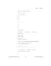
Input Names
-----------
Rotor Angle
Output Names
------------
Horizontal v
System is continuous
The system has poles and zeros in the right half of the complex plane and
therefore is open-loop unstable. Checking the pole and zero locations
confirms this:
ol_poles=poles(ssys)
ol_poles (a column vector) =
0.118256 - 0.367817 j
0.118256 + 0.367817 j
-0.656513
ol_zeros=zeros(ssys)
ol_zeros (a column vector) =
0.25 + 2.4975 j
0.25 - 2.4975 j
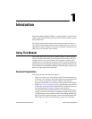
Try to stabilize the system using feedback compensation. You have two
major performance goals to achieve through your controller design: first,
the system must be closed-loop stable, and second, you want the system
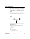
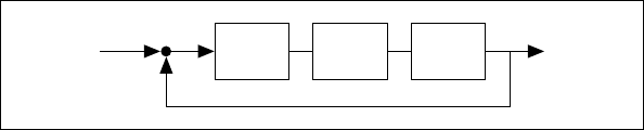
output to track a unit step input. To begin, put two compensators in the
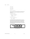
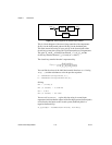
feedforward path of the closed-loop system. Figure 1-1 is a closed-loop
block diagram of helicopter system H(s) with compensators K
1
(s) and K
2
(s)
in the feedforward path.
Figure 1-1. Block Diagram of Helicopter System H(s) with Compensators K
1
(s) and
K
2
(s) in the Feedforward Path
U(s) Y(s)
G(s) K
1
(s) K
2
(s)
+
–