


9
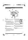
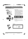
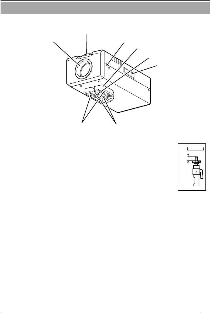
Controls, Connectors and Indicators
(Front, top and side views)
1 Lens mount
The mount for attaching a lens. Either a C-
mount or a CS-mount lens can be used.
2 Back-focus adjustment ring
The ring for adjusting back-focus and chang-
ing the mount method. For adjusting back-fo-
cus or changing the mount method, loosen
the back-focus locking screw (3) by turning it
counterclockwise and, after the operation, fix
it by turning it clockwise. At the factory, VN-
C10 is optimized for attaching a CS mount
lens.
3 [BF LOCK] locking screw
This serves to fix the back focus-adjustment
ring.
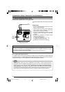
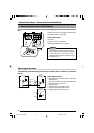
4 Bracket for camera mounting.
At the factory, the bracket is attached on the
bottom of the camera. According to the instal-
lation condition, this can be attached at the
top. Use the screws (7) for attaching the
bracket to the camera.
5 Screw hole (1/4-20UNC)
For attaching the camera to
a fixer or a pan/tilt unit. The
screw length must not ex-
ceed 7 mm. If a longer screw
is used, the internal parts of
the camera may be dam-
aged.
6 Fall-preventive holes
For installing the camera securely, use these
holes to prevent it from falling off.
7 Screws for the bracket (x 2: M2.6 X 6 mm)
Screws of the length of 6 mm should be used.
A longer screw may damage the internal parts.
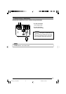
8 [MAC address]
Physical address unique to the unit. Cannot
be changed.
8
1
2
3
4
5
6
7
MAX.
7 mm
VN-C10_E_01-43.pm65e 14/04/03, 10:13 AM9