


16
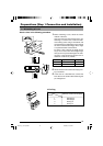
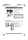
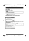
1-4 Connecting the Alarm I/O Terminals
Connect the alarm I/O terminals with external equipment such as a sensor, buzzer,
etc.
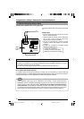
Input Requirements
• No-voltage relay “A-contact” input or NPN open
collector input
(A-contact: Contact is normally open and closes
when the alarm is turned on.)
• Active low level
• Latch/Momentary (at least 500 ms)
• Circuit current at low level: 0.6 mA
•Voltage applied at high level: 3.3 V
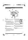
Alarm Input Terminal
This terminal is for connecting with a sensor, infrared, door or metallic, or a manual
switch.
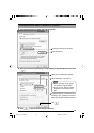
CLASS 2 ONLY For USA
ISOLATED POWER ONLY
POWER
G
2
21
1
OUT COM
ALARM
DC12V
AC24V
OUTPUT
INPUT
PUSH
For EUROPE
10BASE-T/100BASE-TX
For USA
DO NOT CONNECT TO THE
TELEPHONE NETWORK
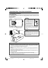
Push
VN-C10
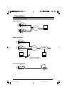
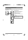
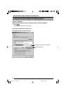
Sensor
Connection
Example 1
Terminal 1 or 2
OUT
R
DC3.3V
(Alarm input equivalent circuit)
Grounding
terminal
GND
0.6mA
R
VCC
Sensor
Connection
Example 2
OUT
GND
3.3V
Relay, switch etc.
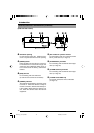
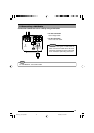
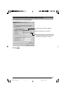
Press the buttons for connecting or disconnect-
ing cables as shown on the left.
Cable Specifications
50 m max.
UL1007, UL1015 or equivalent
AWG #22 to AWG #18 or equivalent
Caution
Due to external noise, the camera may not
work properly even if the length of the cable
is less than 50 m. If this occurs, use a
shielded cable or keep the cable away from
the noise source.
Preparations (Step 1 Connection and Installation)
VN-C10_E_01-43.pm65e 14/04/03, 10:13 AM16