


40
XIX. MAINTENANCE
HIGH VOLTAGE!
T
O
AVOID
PERSONAL
INJURY
OR
DEATH
DUE
TO
ELECTRICAL
SHOCK
,
DISCONNECT
ELECTRICAL
POWER
BEFORE
PERFORMING
ANY
MAINTENANCE
. I
F
YOU
MUST
HANDLE
THE
IGNITER
,
HANDLE
WITH
CARE
. T
OUCHING
THE
IGNITER
ELEMENT
WITH
BARE
FINGERS
,
ROUGH
HANDLING
OR
VIBRATION
COULD
DAMAGE
THE
IGNITER
RESULTING
IN
PREMATURE
FAILURE
. O
NLY
A
QUALIFIED
SERVICER
SHOULD
EVER
HANDLE
THE
IGNITER
.
WARNING
ANNUAL INSPECTION
The furnace should be inspected by a qualified installer, or service
agency at least once per year. This check should be performed at the
beginning of the heating season. This will ensure that all furnace com-
ponents are in proper working order and that the heating system func-
tions appropriately. Pay particular attention to the following items. Re-
pair or service as necessary.
• Flue pipe system. Check for blockage and/or leakage. Check
the outside termination and the connections at and internal
to the furnace.
• Heat exchanger. Check for corrosion and/or buildup within
the heat exchanger passageways.
• Burners. Check for proper ignition, burner flame, and flame
sense.
• Drainage system. Check for blockage and/or leakage.
Check hose connections at and internal to furnace.
• Wiring. Check electrical connections for tightness and/or
corrosion. Check wires for damage.
• Filters.
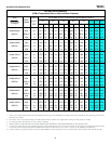
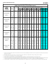
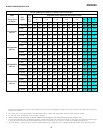
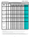
FILTERS
T
O
ENSURE
PROPER
UNIT
PERFORMANCE
,
ADHERE
TO
THE
FILTER
SIZES
GIVEN
IN
THE
RECOMMENDED
M
INIMUM
F
ILTER
S
IZE
T
ABLE
OR
S
PECIFICATION
S
HEET
APPLICABLE
TO
YOUR
MODEL
*
CAUTION
*NOTE: Please contact your distributor or our website for the
applicable Specification Sheet referred to in this manual.
MAINTENANCE
Improper filter maintenance is the most common cause of inad-
equate heating or cooling performance. Filters should be cleaned
(permanent) or replaced (disposable) every two months or as re-
quired. When replacing a filter, it must be replaced with a filter of
the same type and size.
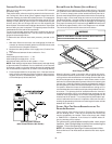
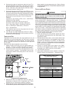
FILTER REMOVAL
Depending on the installation, differing filter arrangements can be
applied. Filters can be installed in either the central return register
or a side panel external filter rack (upflow only). A media air filter or
electronic air cleaner can be used as an alternate filter. Follow the
filter sizes given in the Recommended Minimum Filter size table to
ensure proper unit performance.
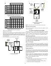
To remove filters from an external filter rack in an upright upflow instal-
lation, follow the directions provided with external filter rack kit.
HORIZONTAL U NIT F ILTER R EMOVAL
Filters in horizontal installations are located in the central return regis-
ter or the ductwork near the furnace.
To remove:
1. Turn OFF electrical power to furnace.
2. Remove filter(s) from the central return register or ductwork.
3. Replace filter(s) by reversing the procedure for removal.
4. Turn ON electrical power to furnace.
MEDIA AIR FILTER OR ELECTRONIC AIR CLEANER REMOVAL
Follow the manufacturer’s directions for service.
BURNERS
Visually inspect the burner flames periodically during the heating sea-
son. Turn on the furnace at the thermostat and allow several minutes
for flames to stabilize, since any dislodged dust will alter the flames
normal appearance. Flames should be stable, quiet, soft, and blue
(dust may cause orange tips but they must not be yellow). They should
extend directly outward from the burners without curling, floating, or
lifting off. Flames must not impinge on the sides of the heat exchanger
firing tubes.
INDUCED DRAFT AND CIRCULATOR BLOWERS
The bearings in the induced draft blower and circulator blower motors
are permanently lubricated by the manufacturer. No further lubrication
is required. Check motor windings for accumulation of dust which
may cause overheating. Clean as necessary.
CONDENSATE TRAP AND DRAIN SYSTEM (QUALIFIED SERVICER
ONLY)
Annually inspect the drain tubes, drain trap, and field-supplied drain
line for proper condensate drainage. Check drain system for hose
connection tightness, blockage, and leaks. Clean or repair as
necessary.
FLAME SENSOR (QUALIFIED SERVICER ONLY)
Under some conditions, the fuel or air supply can create a nearly
invisible coating on the flame sensor. This coating acts as an
insulator causing a drop in the flame sense signal. If the flame
sense signal drops too low the furnace will not sense flame and
will lock out. The flame sensor should be carefully cleaned by a
qualified servicer using emery cloth or steel wool. Following clean-
ing, the flame sense signal should be 1 to 6 microamps at 115
volts.
IGNITER (QUALIFIED SERVICER ONLY)
If the igniter and the surrounding air are at about 70°F and the
igniter wires are not connected to any other electrical components,
the resistance of the igniter should not exceed 75 ohms. If it does,
the igniter should be replaced.
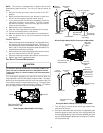
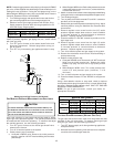
FLUE PASSAGES (QUALIFIED SERVICER ONLY)
The heat exchanger flue passageways should be inspected at the
beginning of each heating season. If necessary, clean the pas-
sageways as outlined below.
1. Turn OFF the electrical power and gas supply to the furnace.
2. Disconnect the gas line and remove the burner/ manifold
assembly by removing the screws securing the assembly
to the partition panel.
3. Disconnect the flue pipe system from the induced draft
blower.
4. Remove the induced draft blower and, drain and pressure
tap hoses from the recuperator coil front cover.
5. Remove the recuperator coil front cover to expose the coil tubes
and turbulators.