


32
CHECKING DUCT STATIC
Refer to your furnace rating plate for the maximum ESP (external
duct static) rating.
Total external static refers to everything external to the furnace cabi-
net. Cooling coils, filters, ducts, grilles, registers must all be consid-
ered when reading your total external static pressure. The supply duct
pressure must be read between the furnace and the cooling coil. This
reading is usually taken by removing the “A” shaped block off plate
from the end on the coil; drilling a test hole in it and reinstalling the
block off plate. Take a duct static reading at the test hole. Tape up the
test hole after your test is complete. The negative pressure must be
read between the filter and the furnace blower.
Too much external static pressure will result in insufficient air that can
cause excessive temperature rise. This can cause limit switch trip-
ping and heat exchanger failure.
To determine total external duct static pressure, proceed as fol-
lows;
1. With clean filters in the furnace, use a draft gauge (inclined ma-
nometer) to measure the static pressure of the return duct at the
inlet of the furnace. (Negative Pressure)
2. Measure the static pressure of the supply duct. (Positive Pres-
sure)
3. The difference between the two numbers is .4” w.c.
Example:
static reading from return duct = -.1" w.c.
static reading from supply duct = .3" w.c.
total external static pressure on this system = .4" w.c.
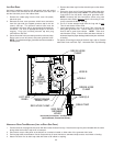
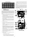
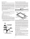
NOTE: Both readings may be taken simultaneously and read directly
on the manometer if so desired. If an air conditioner coil or Electronic
Air Cleaner is used in conjunction with the furnace, the readings must
also include theses components, as shown in the following drawing.
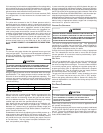
4. Consult proper tables for the quantity of air. If the total external
static pressure exceeds the maximum listed on the furnace rat-
ing plate, check for closed dampers, registers, undersized and/
or oversized poorly laid out duct work.
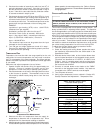
Checking Static Pressure
(80% Furnace Shown, 90% Similar)
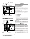
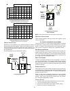
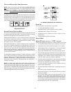
BOTTOM RETURN AIR OPENING [UPFLOW MODELS]
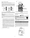
The bottom return air opening on upflow models utilizes a “lance and
cut” method to remove sheet metal from the duct opening in the base
pan. To remove, simply press out the lanced sections by hand to ex-
pose the metal strips retaining the sheet metal over the duct opening.
Using tin snips, cut the metal strips and remove the sheet metal to
free the duct flanges. Using the scribe line along the duct flange as a
guide, unfold the duct flanges around the perimeter of the opening
using a pair of seamer pliers or seamer tongs. NOTE: Airflow area will
be reduced by approximately 18% if duct flanges are not unfolded.
This could cause performance issues and noise issues.
E
DGES
OF
SHEET
METAL
HOLES
MAY
BE
SHARP
. U
SE
GLOVES
AS
A
PRECAUTION
WHEN
REMOVING
HOLE
PLUGS
.
WARNING
CUT FOUR CORNERS
AFTER REMOVING SHEET
METAL
CUT USING TIN SNIPS
PRESS OUT BY HAND
SCRIBE LINES OUTLINING
DUCT FLANGES
Duct Flange Cut Outs
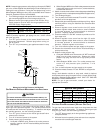
When the furnace is used in connection with a cooling unit, the fur-
nace should be installed in parallel with or on the upstream side of the
cooling unit to avoid condensation in the heating element. With a par-
allel flow arrangement, the dampers or other means used to control
the flow of air must be adequate to prevent chilled air from entering the
furnace and, if manually operated, must be equipped with means to
prevent operation of either unit unless the damper is in the full heat or
cool position. When the furnace is installed without a cooling coil, it is
recommended that a removable access panel be provided in the out-
let air duct. This opening shall be accessible when the furnace is
installed and shall be of such a size that the heat exchanger can be
viewed for visual light inspection or such that a sampling probe can be
inserted into the air stream. The access panel must be made to pre-
vent air leaks when the furnace is in operation. When the furnace is
heating, the temperature of the return air entering the furnace must be
between 55°F and 100°F.
FILTERS - READ THIS SECTION BEFORE INSTALLING THE
RETURN A IR D UCTWORK
Filters must be used with this furnace. Discuss filter maintenance
with the building owner. Filters do not ship with this furnace, but
must be provided by the installer. Filters must comply with UL900
or CAN/ULCS111 standards. If the furnace is installed without fil-
ters, the warranty will be voided.
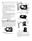
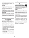
On upflow units, guide dimples locate the side return cutout
locations. Use a straight edge to scribe lines connecting the
dimples. Cut out the opening on these lines.
NOTE: An undersized opening will cause reduced airflow.
Refer to Minimum Filter Area tables to determine filter area require-
ments.