


27
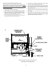
Furnace
Control
Remote Condensing Unit
Heating/Cooling
Room Thermostat
Y
Y1
Y1 Y2
Lo-Heat
Hi-Heat
Cool
Line-H
T4
T2
T3
T5
ECO-TECH
MOTOR
Field
Supplied
Relay
Y2
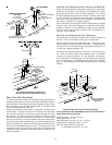
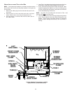
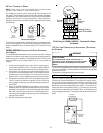
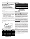
Field Wiring for GME95 /AMEH96 Furnacewith 2-Stage
Condenser
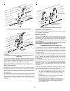
115 VOLT LINE CONNECTION OF ACCESSORIES (ELECTRONIC
AIR C LEANER)
HIGH VOLTAGE!
T
O
AVOID
PERSONAL
INJURY
OR
DEATH
DUE
TO
ELECTRICAL
SHOCK
,
DISCONNECT
ELECTRICAL
POWER
BEFORE
SERVICING
OR
CHANGING
ANY
ELECTRICAL
WIRING
.
WARNING
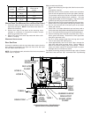
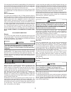
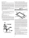
The furnace’s integrated control module is equipped with line voltage
accessory terminals for controlling power to an optional field-supplied
electronic air cleaner.
The accessory load specifications are as follows:
Electronic Air Cleaner 1.0 Amp maximum at 120 VAC
Turn OFF power to the furnace before installing any accessories.
Follow the air cleaner manufacturers’ instructions for locating, mount-
ing, grounding, and controlling these accessories. Accessory wiring
connections are to be made through the 1/4" quick connect terminals
provided on the furnace integrated control module. The electronic air
cleaner hot terminal is identified as EAC-H. The electronic air cleaner
neutral terminal is identified as LINE NEUTRAL. All field wiring must
conform to applicable codes. Connections should be made as shown
below.
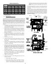
ELECTRONIC
A
IR CLEANER
OPTIONAL
A
CCESSORIES
12 PIN
CONNECTOR
120 VAC
NEUTRAL
TERMINALS
120 VAC
HOT AND
PARK
TERMINALS
INTEGRATED
CONTROL
MODULE
Accessories Wiring
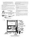
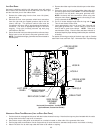
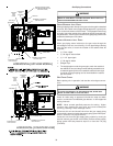
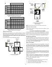
24 VOLT THERMOSTAT WIRING
NOTE: Wire routing must not interfere with circulator blower
operation, filter removal, or routine maintenance.
Low voltage connections can be made through either the right or left
side panel. Thermostat wiring entrance holes are located in the blower
compartment. Wire routing must not to interfere with circulator blower
operation, filter removal, or routine maintenance. Refer to the follow-
ing figure for thermostat connections to the integrated control module
terminal strip.
W
W
W
Y
Y
Y
C
C
R
R
R
G
G
W
Y
C
R
G
HEATING
ROOM
THERMOSTAT
HEATING AND
COOLING ROOM
THERMOSTAT
FURNACE
FURNACE
REMOTE
CONDENSING
UNIT
Thermostat Diagram
This furnace is equipped with a 40 VA transformer to facilitate use with
most cooling equipment. Consult the wiring diagram, located on the
blower compartment door, for further details of 115 Volt and 24 Volt
wiring.
GME95/AMEH96 FURNACE WITH 2-STAGE CONDENSER
FIELD WIRING
The GME95/AMEH96 model furnaces may be used with a 2-stage
outdoor air conditioner. A two stage cooling/single stage gas heat ther-
mostat is required, in addition to a field supplied relay. The relay must
have a 24VAC coil and contacts rated for up to 1 horse power at
125VAC.
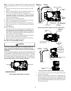
1. Install the field supplied relay on the control mounting panel
near the furnace ignition control. The relay should be installed
such that the motor leads will reach the relay contact terminals.
2. Connect the “Y2” (high stage cool) thermostat terminal to one
coil terminal of the field supplied relay. Connect the other field
supplied relay coil terminal to the “C” terminal on the furnace
ignition control. Typical 18AWG thermostat wire may be used.
3. Connect the common terminal of the field supplied relay to the
“LINE-H” terminal on the furnace ignition control. Use wiring
having copper conductors only and a temperature rating of at
least 105°C.
4. Using the GME95/AMEH96 airflow tables in this manual,
determine the motor speed tap needed to deliver the required
high stage cooling airflow. Connect the selected motor speed
tap to the normally open terminal on the field supplied relay.
Use wiring having copper conductors only and a temperature
rating of at least 105°C.
5. See the following wiring schematic.