


21
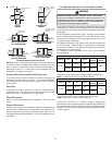
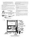
• If an air conditioning coil is installed with the furnace, a
common drain may be used. An open tee must be
installed in the drain line, near the cooling coil, to relieve
positive air pressure from the coil’s plenum. This is
necessary to prohibit any interference with the function of
the furnace’s drain trap.
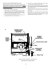
NOTE: In vertical installations, air conditioning coil condensate may
drain into the furnace trap as long as there is a trap between the coil and
the furnace trap and the drain pipe is not terminating below the water
level of the furnace trap.
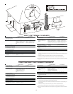
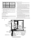
STANDARD RIGHT OR LEFT SIDE DRAIN HOSE CONNECTIONS
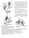
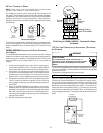
All installations positions require the use of the drain trap, hoses, tubes,
and clamps. The following quantity of hoses, tubes, and hose clamps
are provided with the unit.
DRAIN TRAP
QTY: 1
GREEN
HOSE CLAMPS
QTY: 3
SILVER
HOSE CLAMP
QTY: 1
TUBE 2
QTY: 2
TUBE 1
QTY: 1
HOSE B
QTY: 1
HOSE A
QTY: 1
RED
HOSE CLAMP
QTY: 1
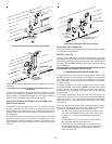
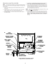
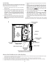
Hose and Tube Identification
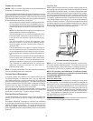
In a upright installation drain hoses are connected to drain ports on the
rubber elbow and the recuperator coil front cover. The drain lines are
then routed through the right side panel and into the drain trap secured
to the outside of the cabinet.
NOTE: Refer to Alternate Vent/Flue Hose Connections for upright
installations using an alternate vent/flue outlet.
1. Remove the rubber plug from the right side of the front cover
drain port.
2. Secure Hose A to front cover drain port with a red hose
clamp. Route hose to rear side panel grommet hole.
3. Cut and remove 1/4 inch from the end of the drain port on
the rubber elbow.
4. Insert Tube 1 into rubber elbow drain port and secure with
silver hose clamp. Angle tube outward toward front of
furnace.
5. Cut 17 3/4 inches from the long end of Hose B and discard.
Secure the remaining hose to Tube 1 with a green hose
clamp. Route the other end of Hose B to front right side
panel grommet hole.
For details concerning mounting of the drain trap, refer to Vertical
Drain Trap Mounting.
6. Insert short end of each of tube 2 through side panel
grommet holes. Secure tubes to hoses A and B with green
hose clamps. Ensure hoses and tubes maintain a
downward slope for proper drainage and that they are not
kinked or binding.
DRAIN
TRAP
FRONT
COVER
DRAIN PORT
TUBE(S) 2
GREEN
HOSE
CLAMPS
(3 PLACES)
RIGHT SIDE
PANEL
RUBBER ELBOW
DRAIN PORT
TUBE 1
SIDE PANEL
GROMMET
HOLES
HOSE
B
HOSE
A
RUBBER
ELBOW
RED HOSE
CLAMP
SILVER HOSE CLAMP
Upright “Standard” Connections -Right Side
(Upflow Shown, Counterflow Similar)