


33
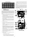
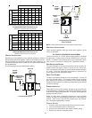
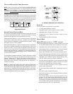
600 800 1000 1200 1400 1600 2000
040_3BXA
0453BXA
194* 194* 240 288 --- --- ---
060_3BXA
0703BXA
--- 324* 324* 324* 336 --- ---
0704CXA --- --- 291* 291* 336 384 ---
0904CXA --- --- 432* 432* 432* 432* ---
080_5CXA
0905DXA
--- --- --- 388* 388* 388* 480
100_5DXA
1155DXA
--- --- --- 486* 486* 486* 486*
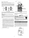
Input__Airflow
COOLING AIRFLOW REQUIREMENT (CFM)
*Minimum filter area dictated by heating airflow requirement.
Permanent Minimum Filter Area (sq. in)
[Based on a 600 ft/min filter face velocity]
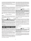
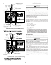
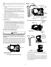
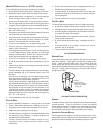
600 800 1000 1200 1400 1600 2000
040_3BXA
0453BXA
388* 388* 480 576 --- --- ---
060_3BXA
0703BXA
--- 647* 647* 647* 672 --- ---
0704CXA 583* 583* 672 768
0904CXA --- --- 863* 863* 863* 863* ---
080_5CXA
0905DXA
--- --- --- 777* 777* 777* 960
100_5DXA
1155DXA
--- --- --- 971* 971* 971* 971*
Input__Airflow
COOLING AIRFLOW REQUIREMENT (CFM)
*Minimum filter area dictated by heating airflow requirement.
Disposable Minimum Filter area (sq. in)
[Based on 300 ft/min filter face velocity]
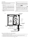
UPRIGHT INSTALLATIONS
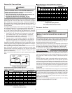
Depending on the installation and/or customer preference, differing
filter arrangements can be applied. Filters can be installed in the cen-
tral return register or a side panel external filter rack kit (upflows). As
an alternative a media air filter or electronic air cleaner can be used as
the requested filter.
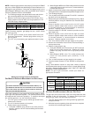
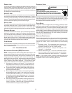
The following figure shows possible filter locations.
FILTER
AIR FLOW
CENTRAL
RETURN
GRILLE
FILTER
SIDE RETURN
EXTERNAL FILTER
RACK KIT
(EITHER SIDE)
Possible Upright Upflow
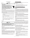
FILTER
FILTER
AIR FLOW
FILTER
ACCESS
DOOR
CENTRAL
RETURN
GRILLE
RETURN
DUCT
FILTE
R
FILTER
SUPPORT
BRACKET
(PROVIDED)
Possible Upright Counterflow
Filter Locations
NOTE: Internal filter retention is not provided on this furnace.
HORIZONTAL INSTALLATIONS
Filters must be installed in either the central return register or in the
return air duct work.
XIV. STARTUP PROCEDURE & ADJUSTMENT
Furnace must have a 115 VAC power supply properly connected
and grounded. Proper polarity must be maintained for correct op-
eration. In addition to the following start-up and adjustment items,
refer to further information in Section XVI, Operational Checks.
HEAT A NTICIPATOR S ETTING
The heat anticipator in the room thermostat must be correctly ad-
justed to obtain the proper number of cycles per hour and to pre-
vent “overshooting” of the setting. Set the heat anticipator setting to
0.7 amps. Follow the thermostat manufacturer’s instructions on
how to adjust the heat anticipator setting.
DRAIN TRAP PRIMING
The drain trap must be primed prior to furnace startup. To prime, fill
the drain trap with water. This ensures proper furnace drainage
upon startup and prohibits the possibility of flue gases escaping
through the drain system. Air conditioning condensate may be drained
into the furnace trap.
FURNACE OPERATION
Purge gas lines of air prior to startup. Be sure not to purge lines into
an enclosed burner compartment. Follow NFPA 54, National Fuel Gas
Code 8.3 for proper purging methods. In Canada, follow approved
purging methods in B149.1
Check for leaks using an approved chloride-free soap and water
solution, an electronic combustible gas detector, or other approved
method. Verify that all required kits (propane gas, high altitude,
etc.) have been appropriately installed.
FURNACE STARTUP
1. Close the manual gas shutoff valve external to the furnace.
2. Turn off the electrical power to the furnace.
3. Set the room thermostat to the lowest possible setting.
4. Remove the burner compartment door.