


15
IX. VENT/FLUE PIPE & COMBUSTION AIR PIPE
GENERAL
F
AILURE
TO
FOLLOW
THESE
INSTRUCTIONS
CAN
RESULT
IN
BODILY
INJURY
OR
DEATH
. C
AREFULLY
READ
AND
FOLLOW
ALL
INSTRUCTIONS
GIVEN
IN
THIS
SECTION
.
WARNING
U
PON
COMPLETION
OF
THE
FURNACE
INSTALLATION
,
CAREFULLY
INSPECT
THE
ENTIRE
FLUE
SYSTEM
BOTH
INSIDE
AND
OUTSIDE
OF
THE
FURNACE
TO
ASSURE
IT
IS
PROPERLY
SEALED
. L
EAKS
IN
THE
FLUE
SYSTEM
CAN
RESULT
IN
SERIOUS
PERSONAL
INJURY
OR
DEATH
DUE
TO
EXPOSURE
TO
FLUE
PRODUCTS
,
INCLUDING
CARBON
MONOXIDE
.
WARNING
A condensing gas furnace achieves its high level of efficiency by ex-
tracting almost all of the heat from the products of combustion and
cooling them to the point where condensation takes place. Because
of the relatively low flue gas temperature and water condensation re-
quirements, PVC pipe is used as venting material.
This furnace must not be connected to Type B, BW, or L vent or vent
connector, and must not be vented into any portion of a factory built
or masonry chimney except when used as a pathway for PVC as
described later in this section. Never common vent this appliance
with another appliance or use a vent which is used by a solid fuel
appliance. Do not use commercially available “no hub connec-
tors” other than those shipped with this product.
It is the responsibility of the installer to follow the manufacturers’
recommendations and to verify that all vent/flue piping and con-
nectors are compatible with furnace flue products. Additionally, it
is the responsibility of the installer to ensure that all piping and
connections possess adequate structural integrity and support to
prevent flue pipe separation, shifting, or sagging during furnace
operation.
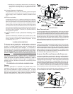
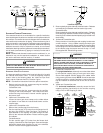
DUAL C ERTIFICATION: NON-DIRECT/DIRECT V ENT
This furnace is dual certified and may be installed as a non-direct
vent (single pipe) or direct vent (dual pipe) appliance. A non-direct
vent installation requires only a vent/flue pipe, while a direct vent
installation requires both a vent/flue pipe and a combustion air
intake pipe. Refer to the appropriate section for details concerning
piping size, length, number of elbows, furnace connections, and
terminations.
MATERIALS AND JOINING METHODS
T
O
AVOID
BODILY
INJURY
,
FIRE
OR
EXPLOSION
,
SOLVENT
CEMENTS
MUST
BE
KEPT
AWAY
FROM
ALL
IGNITION
SOURCES
(
I
.
E
., S
PARKS
,
OPEN
FLAMES
,
AND
EXCESSIVE
HEAT
)
AS
THEY
ARE
COMBUSTIBLE
LIQUIDS
. A
VOID
BREATHING
CEMENT
VAPORS
OR
CONTACT
WITH
SKIN
AND
/
OR
EYES
.
WARNING
Two- or three-inch nominal diameter PVC Schedule 40 pipe meet-
ing ASTM D1785, PVC primer meeting ASTM F656, and PVC sol-
vent cement meeting ASTM D2564 specifications must be used.
Fittings must be DWV type fittings meeting ASTM D2665 and ASTM
D3311. Carefully follow the manufacturer’s instructions for cutting,
cleaning, and solvent cementing of PVC.
The use of Schedule 40 PVC or ABS cellular core (Foam Core) plas-
tic pipe is also acceptable as a flue/vent and intake pipe material. PVC
primer meeting ASTM F656 and PVC solvent cement meeting ASTM
D2564 specifications must be used. Fittings must be DWV type fit-
tings meeting ASTM D2665 and ASTM D3311. Carefully follow the
manufactures instructions for cutting, cleaning and solvent cement-
ing of PVC.
In addition to PVC and ABS pipe and fittings, Innoflue
®
by
Centrotherm Eco Systems and PolyPro
®
by M&G Duravent are also
approved vent and combustion air materials for installations in the
U.S.A. and Canada. Manufacturers Installation instructions for these
products must be followed. These products have specific instructions
for installing, joining and terminating. Do not mix materials or compo-
nents of one manufacturer with materials or components of another
manufacturer.
For Canadian installations; all PVC pipe, fittings and joining mate-
rials must be UL S636 listed.
As an alternative to PVC pipe, primer, solvent cement, and fittings,
ABS materials which are in compliance with the following specifi-
cations may be used. Two-or-three-inch ABS Schedule 40 pipe
must meet ASTM D1527 and, if used in Canada, must be CSA
listed. Solvent cement for ABS to ABS joints must meet ASTM
D2235 and, if used in Canada, must be CSA listed. The solvent
cement for the PVC to ABS transition joint must meet ASTM D3138.
Fittings must be DWV type fittings meeting ASTM D2661 and ASTM
D3311 and, if used in Canada, must be CSA listed. Carefully
follow the pipe manufacturers’ instructions for cutting, cleaning,
and solvent cementing PVC and/or ABS.
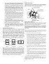
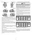
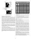
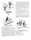
All 90° elbows must be medium radius (1/4 bend DWV) or long
radius (Long sweep 1/4 bend DWV) types conforming to ASTM
D3311. A medium radius (1/4 bend DWV) elbow measures 3 1/
16” minimum from the plane of one opening to the centerline of the
other opening for 2” diameter pipe, and 4 9/16” minimum for 3”
pipe.
PROPER VENT/FLUE AND COMBUSTION A IR PIPING P RACTICES
Adhere to these instructions to ensure safe and proper furnace
performance. The length, diameter, and number of elbows of the
vent/flue pipe and combustion air pipe (when applicable) affects
the performance of the furnace and must be carefully sized. All
piping must be installed in accordance with local codes and these
instructions.
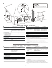
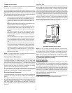
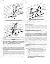
Piping must be adequately secured and supported to prohibit sag-
ging, joint separation, and/or detachment from the furnace. Hori-
zontal runs of vent/flue piping must be supported every three to five
feet and must maintain a 1/4 inch per foot downward slope, back
towards the furnace, to properly return condensate to the furnace’s
drain system. Allowances should be made for minor expansion
and contraction due to temperature variations. For this reason,
particular care must be taken to secure piping when a long run is
followed by a short offset of less than 40 inches.
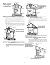
Precautions should be taken to prevent condensate from freez-
ing inside the vent/flue pipe and/or at the vent/flue pipe termina-
tion. It is our recommendation that all vent/flue piping exposed to
temperatures below 35°F for extended periods of time should be
insulated with 1/2” thick closed cell foam. Also all vent/flue piping
exposed outdoors in excess of the terminations shown in this
manual (or in unheated areas) should be insulated with 1/2” thick
closed cell foam. Inspect piping for leaks prior to installing insu-
lation.