


13
VIII. PROPANE GAS /HIGH ALTITUDE INSTALLATIONS
P
OSSIBLE
PROPERTY
DAMAGE
,
PERSONAL
INJURY
OR
DEATH
MAY
OCCUR
IF
THE
CORRECT
CONVERSION
KITS
ARE
NOT
INSTALLED
. T
HE
APPROPRIATE
KITS
MUST
BE
APPLIED
TO
ENSURE
SAFE
AND
PROPER
FURNACE
OPERATION
. A
LL
CONVERSIONS
MUST
BE
PERFORMED
BY
A
QUALIFIED
INSTALLER
OR
SERVICE
AGENCY
.
WARNING
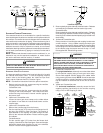
This furnace is shipped from the factory configured for natural gas at
standard altitude. Propane gas installations require an orifice change
to compensate for the energy content difference between natural and
propane gas.
For furnaces being converted to LP gas, it is strongly recommended
that a LPLP03 kit also be installed. The use of this kit will prevent
the furnace from firing when the LP gas supply pressure is too low
to support proper combustion.
High altitude installations may require both a pressure switch and
an orifice change. These changes are necessary to compensate
for the natural reduction in the density of both the gas fuel and the
combustion air at higher altitude.
For installations above 7000 feet, please refer to your distributor
for required kit(s).
Altitude Gas Kit Orifice
Manifold
Pressure
Pressure
Switch
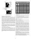
*MH95, ACSH96, GCH95, GCH9 GAS ORIFICE CHART
Natural
Propane
2 LPM-06* supports both Honeywell and White-Rodgers 2-stage valves
NOTE:
In Canada, gas furnaces are certified to 4500 feet.
0-7000
None
LPM-06*
2
#43
#55
3.5" w.c.
10.0" w.c.
None
Altitude Gas Kit Orifice
Manifold
Pressure
Pressure
Switch
2
LPM-06* supports both Honeywell and White-Rodgers 2-stage valves
NOTE:
In Canada, gas furnaces are certified to 4500 feet.
0-7000
None
LPM-06*
2
#45
#55
3.5" w.c.
10.0" w.c.
None
AMEH96, GME95 GAS ORIFICE CHART
Natural
Propane
Contact the distributor for a tabular listing of appropriate
manufacturer’s kits for propane gas and/or high altitude installations.
The indicated kits must be used to insure safe and proper furnace
operation. All conversions must be performed by a qualified installer,
or service agency.
AIR
DISCHARGE
AIR
DISCHARGE
AIR
DISCHARGE
Bottom
Return
Duct
Connection
Bottom
Return
Duct
Connection
Bottom
Return
Duct
Connection
Side
Return
Duct
Connection
Side
Return
Duct
Connection
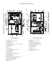
UPFLOW
UPRIGHT
UPFLOW HORIZONTAL
RIGHT AIR DISCHARGE
UPFLOW HORIZONTAL
LEFT AIR DISCHARGE
ALTERNATE FLUE
PIPE LOCATION
ALTERNATE FLUE PIPE
LOCATION
AIR
DISCHARGE
AIR
DISCHARGE
AIR
DISCHARGE
Bottom
Return
Duct
Connection
Bottom
Return
Duct
Connection
Bottom
Return
Duct
Connection
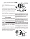
COUNTERFLOW
UPRIGHT
COUNTERFLOW HORIZONTAL
RIGHT AIR DISCHARGE
COUNTERFLOW HORIZONTAL
LEFT AIR DISCHARGE
ALTERNATE FLUE AND
COMBUSTION AIR PIPE
LOCATIONS
ALTERNATE FLUE AND
COMBUSTION AIR PIPE
LOCATIONS
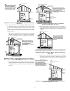
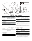
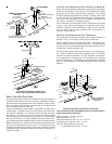
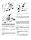
Recommended Installation Positions
NOTE: Alternate “vertical” piping connections can not be used when
an upflow furnace is installed with supply air discharging to the
right, or when a counterflow furnace is installed with supply air
discharging to the left. In either case, use the standard flue and
combustion air piping connections.
ALTERNATE E LECTRICAL AND G AS L INE C ONNECTIONS
This furnace has provisions allowing for electrical and gas line
connections through either side panel. In horizontal applications
the connections can be made either through the “top” or “bottom”
of the furnace.
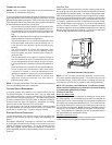
DRAIN PAN
A drain pan must be provided if the furnace is installed above a
conditioned area. The drain pan must cover the entire area under
the furnace (and air conditioning coil if applicable).
FREEZE PROTECTION
Refer to Horizontal Applications and Conditions - Drain Trap and
Lines.
FURNACE SUSPENSION
If the furnace is installed in a crawl space it must be suspended from
the floor joist or supported by a concrete pad. Never install the fur-
nace on the ground or allow it to be exposed to water. Refer to Loca-
tion Requirements and Considerations - Furnace Suspension for fur-
ther details.