


38
(MODE DIP SWITCH IS SET TO “2 STG” POSITION)
The normal operational sequence in sequence is as follows:
• R and W thermostat contacts close, initiating a call for heat.
• Integrated control module performs safety circuit checks.
• Induced draft blower is energized for 15 second prepurge
period causing pressure switch contacts to close.
• Igniter warm up begins after 15 second prepurge expires.
• Low and high-stage gas valves open at end of igniter warm
up period, delivering gas to burners and establishing flame.
• High-stage gas valve closes after five seconds; low-stage
gas valve remains open.
• Integrated control module monitors flame presence. Gas valve
will remain open only if flame is detected.
• Circulator blower is energized on low heat speed following a
fixed thirty second blower on delay. Electronic air cleaner
terminals are energized with circulator blower.
• Furnace is now operating in low-stage heating mode.
• Furnace operates; integrated control module monitors
safety circuits continuously.
• If low-stage delay period expires, control will shift operation
from low-stage heating mode operation to high-stage
heating mode operation. Control will energize circulator
blower high heat speed and high stage gas valve.
• Furnace is now operating in high-stage heating mode.
• R and W thermostat contacts open, completing the call for
heat.
• Induced draft blower is de-energized following a fifteen
second post purge.
• Circulator blower is de-energized following a heat off delay
period (selectable 100 or 150 seconds; factory set at 150
seconds).
If the furnace is operating in the low-stage heating mode
when thermostat contacts open, circulator remains at low
heat speed for the selected delay off period.
If the furnace is operating in high-stage heating mode when
the thermostat contacts open, the circulator blower remains
at high heat speed for thirty seconds. The circulator blower
then switches to low heat speed for the remainder of the
selected heat off delay period. For example, the selected
heat off delay period is 150 seconds. The circulator blower
operates at high heat for 30 seconds and at low speed for
150 - 30 = 120 seconds.
• Furnace awaits the next call from thermostat.
COOLING MODE
The normal operational sequence in cooling mode is as follows:
• R and Y thermostat contacts close, initiating a call for cool.
• Integrated control module performs safety circuit checks.
• Outdoor fan and compressor are energized.
• Circulator blower is energized on cool speed following a fixed
five second on delay. Electronic air cleaner terminals are
energized with circulator blower.
• Furnace circulator blower and outdoor cooling unit run,
integrated control module monitors safety circuits
continuously.
• R and Y thermostat contact open, completing the call for cool.
• Outdoor fan and compressor are de-energized.
• Circulator blower is de-energized following a fixed forty five
second cool off delay period. Electronic air cleaner terminals
are de-energized.
• Furnace awaits the next call from thermostat.
FAN ONLY MODE
The normal operational sequence in fan only mode is as follows:
• R and G thermostat contacts close, initiating a call for fan.
• Integrated control module performs safety circuit checks.
• Circulator blower is energized on low heat speed. Electronic
air cleaner terminals are energized.
• Circulator blower runs, integrated control module monitors
safety circuits continuously.
• R and G thermostat contacts open, completing the call for
fan.
• Circulator blower is de-energized. Electronic air cleaner
terminals are de-energized.
• Furnace awaits the next call from thermostat.
XVI. OPERATIONAL CHECKS
BURNER FLAME
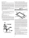
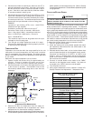
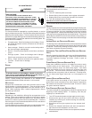
The burner flames should be inspected with the burner compart-
ment door installed. A sight glass is provided for inspection pur-
poses. Flames should be stable, quiet, soft, and blue (dust may
cause orange tips but they must not be yellow). Flames should
extend directly outward from the burners without curling, floating, or
lifting off. Flames must not impinge on the sides of the heat ex-
changer firing tubes.
Check the
Burner Flames for:
1. Stable, soft and blue.
2. Not curling, floating
or lifting off.
Burner Flame
XVII. SAFETY CIRCUIT DESCRIPTION
GENERAL
A number of safety circuits are employed to ensure safe and proper
furnace operation. These circuits serve to control any potential
safety hazards and serve as inputs in the monitoring and diagno-
sis of abnormal function. These circuits are continuously moni-
tored during furnace operation by the integrated control module.
INTEGRATED CONTROL MODULE
The integrated control module is an electronic device which, if a po-
tential safety concern is detected, the module will take the necessary
precautions and provide diagnostic information through an LED.