


16
TERMINATION LOCATIONS
NOTES: Refer to Location Requirements and Considerations for
combustion air contaminant restrictions.
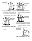
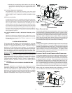
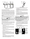
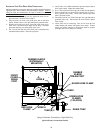
The following bullets and diagram describe the restrictions concern-
ing the appropriate location of vent/flue pipe and combustion air intake
pipe (when applicable) terminations. Refer to Non-Direct Vent (Single
Pipe) Piping and Direct Vent (Dual Pipe) Piping located in this section
for specific details on termination construction.
• All terminations (flue and/or intake) must be located at least
12 inches above ground level or the anticipated snow level.
• Vent terminations (non-direct and direct vent) must terminate
at least 3 feet above any forced air inlet located within 10
feet.
NOTE: This provision does not apply to the combustion air
intake termination of a direct vent application.
• The vent termination of a non-direct vent application must
terminate at least 4 feet below, 4 feet horizontally from, or
1 foot above any door, window, or gravity air inlet into any
building.
• The vent termination of a direct vent application must
terminate at least 12 inches from any opening through
which flue gases may enter a building (door, window, or
gravity air inlet).
• The vent termination of vent pipe run vertically through a
roof must terminate at least 12 inches above the roof line
(or the anticipated snow level) and be at least 12 inches
from any vertical wall (including any anticipated snow build
up).
• A vent termination shall not terminate over public walkways
or over an area where condensate or vapor could create
a nuisance or hazard or could be detrimental to the
operation of regulators, relief valves, or other equipment.
• The combustion air intake termination of a direct vent
application should not terminate in an area which is
frequently dusty or dirty.
NOTE: In Canada, the Canadian Fuel Gas Code takes precedence
over the preceding termination restrictions.
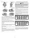
CANADIAN V ENTING R EQUIREMENTS
In Canada, venting must conform to the requirements of the cur-
rent CAN/CSA-B149.1-05 Installation Code. Use only CSA-listed,
ULC-S636 compliant two- or three-inch diameter PVC or ABS pipe,
solvent cement, and fittings throughout. The certified piping should
be clearly marked with the ULC Std “S636” on the pipe and fittings.
Carefully follow the pipe manufacturers’ instructions for cutting,
cleaning, and solvent cementing PVC and/or ABS.
The vent can be run through an existing unused chimney provided
the space between the vent pipe and the chimney is insulated and
closed with a weather-tight, corrosion-resistant flashing.
STANDARD F URNACE C ONNECTIONS
It is the responsibility of the installer to ensure that the piping con-
nections to the furnace are secure, airtight, and adequately sup-
ported.
As shipped, attachment “couplings” for vent/flue and combustion
air intake pipe connections are provided on the furnace’s top cover
(upflow) or basepan (counterflow). To use the standard connec-
tions, field supplied vent/flue pipe and combustion air intake pipe
(when applicable) should be secured directly to the furnace at these
locations.
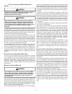
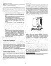
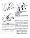
VENT/FLUE PIPE
Vent/flue pipe can be secured to the vent/flue coupling using the rub-
ber coupling and worm gear hose clamps provided with this furnace
(see “Standard Connections” figure). The rubber coupling allows sepa-
ration of the vent/flue pipe from the furnace during servicing. Combus-
tion Air and Vent piping should be routed in a manner to avoid contact
with refrigerant lines, metering devices, condensate drain lines, etc.
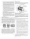
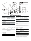
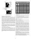
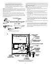
If necessary, clearances may be increased by utilizing two 45 deg.
Long-Sweep Elbows and creating an “S” joint to provide additional
space at connection locations. This joint can be rotated on the fitting
to establish maximum clearance between refrigerant lines, metering
devices, and condensate drain lines, etc. This joint is the equivalent
of one 90 deg. elbow when considering elbow count.
45 DEGREE
LONG-SWEEP
ELBOWS
V
E
N
T
Increased Clearance Configuration
NOTE: Do not use other commercially available “no hub connec-
tors” due to possible material conflicts. The vent/flue pipe can also
be secured using a PVC or ABS elbow or coupling using the ap-
propriate glue (see Section IX, Materials and Joining Methods).
NOTE: For non-direct vent installations, a minimum of one 90°
elbow should be installed on the combustion air intake coupling
to guard against inadvertent blockage.
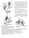
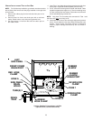
COMBUSTION AIR PIPE
DIRECT VENT I NSTALLATIONS
On upflow units secure the combustion air intake pipe directly to the
air intake coupling. On counterflow units secure the combustion air
intake pipe to the air intake coupling using the rubber coupling and
worm gear hose clamps provided with the unit. The counterflow rub-
ber coupling allows service removal of air intake piping internal to the
furnace blower compartment. NOTE: Because of probable material
conflicts, do not use other commercially available “no hub connec-
tors”. The combustion air intake pipe can also be secured directly to
the counterflow unit air intake pipe coupling.
NON-DIRECT V ENT INSTALLATIONS
A minimum of one 90° elbow should be installed on the combustion air
intake “coupling” to guard against inadvertent blockage.