


19
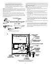
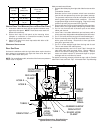
COMBUSTION AIR INTAKE
(OPTIONAL)
*Not required for
single pipe installation
TEE (OPTIONAL)
9
6
”
M
A
X
.
-
3
”
M
I
N
.
R
O
O
F
L
I
N
E
INTAKE
SCREEN
OPTIONAL
12” MIN
HEIGHT DIFFERENCE
BETWEEN
INTAKE AND VENT
12” MIN TO ROOF OR HIGHEST
ANTICIPATED SNOW LEVEL
STRAIGHT
ELBOWS
_______________
VENT/FLUE TEE (
or
45° ELBOW
TURNED DOWN or
90° ELBOW TURNED
DOWN
OPTIONAL)
12" MIN. ABOVE
HIGHEST ANTICIPATED
SNOW LEVEL
12" MIN.
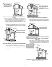
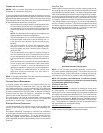
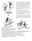
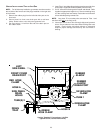
Horizontal Termination (Single Pipe)
Above Highest Anticipated Snow Level
DIRECT VENT (DUAL PIPE) PIPING
The inlet air screens provided in the installation instruction packet are
available for the installer to use in the inlet of the combustion air pipe to
prevent animals from building nests in the combustion air pipe. Instal-
lation of screens, while strongly recommended, is not required and
will not affect performance of the unit.
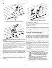
Direct vent installations require both a combustion air intake and a
vent/flue pipe. The pipes may be run horizontally and exit through
the side of the building or run vertically and exit through the roof of
the building. The pipes may be run through an existing unused
chimney; however, they must extend a minimum of 12 inches above
the top of the chimney. The space between the pipes and the chim-
ney must be closed with a weather tight, corrosion resistant flashing.
Both the combustion air intake and a vent/flue pipe terminations must
be in the same atmospheric pressure zone. For details concerning
connection of pipes to the furnace, refer to the Vent/Flue Pipe and
Combustion Pipe - Standard Furnace Connections or Alternate Fur-
nace Connections.
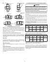
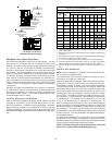
VENT/FLUE AND COMBUSTION AIR PIPE LENGTHS AND DIAMETERS
Refer to the following table for applicable length, elbows, and pipe di-
ameter for construction of the vent/flue and combustion air intake
pipe systems of a direct vent (dual pipe) installation. The number
of elbows tabulated represents the number of elbows and/or tees
in each (Vent/Flue & Combustion Air Intake) pipe. Elbows and/or
tees used in the terminations must be included when determining
the number of elbows in the piping systems.
If the combustion air intake pipe is to be installed above a finished
ceiling or other area where dripping of condensate will be objec-
tionable, insulation of the combustion air pipe may be required.
Use 1/2” thick closed cell foam insulation such as Armaflex™ or
Insultube where required.
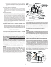
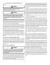
VENT/FLUE AND COMBUSTION AIR PIPE TERMINATIONS
The vent/flue and combustion air pipes may terminate vertically, as
through a roof, or horizontally, as through an outside wall.
Refer to Vent/Flue Pipe and Combustion Pipe - Termination Loca-
tions for details concerning location restrictions. The penetrations
through the roof must be sealed tight with proper flashing such as
is used with a plastic plumbing vent.
Horizontal terminations should be as shown in the following fig-
ure. Refer to Vent/Flue Pipe and Combustion Pipe - Termination
Location for location restrictions. A 2 3/8” diameter wall penetra-
tion is required for 2” diameter pipe. A 3” diameter hole is required
for a 2 1/2” pipe and a 3 1/2” diameter hole is required for 3” diameter
pipe. The wall penetration should be sealed with silicone caulking
material.
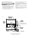
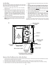
90º OR 45°
ELBOW
SCREEN
(OPTIONAL)
12" MIN. TO GRADE OR
HIGHEST ANTICIPATED
SNOW LEVEL
6” MAX
10”- 24”
4” MIN
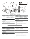
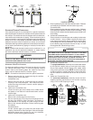
Standard Horizontal Terminations (Dual Pipe)
Vent & Combustion Air Intake Measurements for Standard Hori-
zontal Terminations (Dual Pipe)
Center to center = 10” min / 24” max.
Vertical separation: 0” - 24”
Vent termination from wall = 8” min / 12” max.
Combustion air intake from wall = 6” max.
Vent and intake clearance to ground
or anticipated snow level = 12” min.