


34
NOTE: This furnace is equipped with an ignition device which
automatically lights the burner. Do not try to light the burner by
hand.
5. Move the furnace gas valve manual control to the OFF
position.
6. Wait five minutes then smell for gas. Be sure to check near
the floor as some types of gas are heavier than air.
7. If you smell gas after five minutes, immediately follow the
instructions on page 4 of this manual. If you do not smell
gas after five minutes, move the furnace gas valve manual
control to the ON position.
8. Replace the burner compartment door.
9. Open the manual gas shutoff valve external to the furnace.
10. Turn on the electrical power to the furnace.
11. Adjust the thermostat to a setting above room temperature.
12. After the burners are lit, set the thermostat to desired
temperature.
FURNACE SHUTDOWN
1. Set the thermostat to the lowest setting. The integrated control
will close the gas valve and extinguish flame. Following a 15
second delay, the induced draft blower will be de-energized.
After a 100 or 150 second delay period (field selectable), the
circulator blower will be de-energized.
2. Remove the burner compartment door and move the furnace
gas valve manual control to the OFF position.
3. Close the manual gas shutoff valve external to the furnace.
4. Replace the burner compartment door.
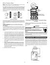
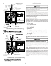
GAS SUPPLY PRESSURE MEASUREMENT
T
O
PREVENT
UNRELIABLE
OPERATION
OR
EQUIPMENT
DAMAGE
,
THE
I
NLET
GAS
SUPPLY
PRESSURE
MUST
BE
AS
SPECIFIED
ON
THE
UNIT
RATING
PLATE
WITH
ALL
OTHER
HOUSEHOLD
GAS
FIRED
APPLIANCES
OPERATING
.
CAUTION
The line pressure supplied to the gas valve must be within the
range specified in the Inlet Gas Supply Pressure table. The supply
pressure can be measured at the gas valve inlet pressure tap or at
a hose fitting installed in the gas piping drip leg. The supply pres-
sure must be measured with the burners operating. To measure
the gas supply pressure, use the following procedure.
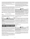
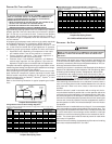
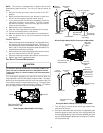
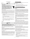
INLET OUTLET
Gas Valve On/Off
Selector Switch
White-Rodgers Model 36G54 (Two-Stage)
Inlet
Pressure
Tap
Low Fire
Regulator
Adjust
M
a
n
o
m
e
t
e
r
M
a
n
o
m
e
t
e
r
H
o
s
e
High Fire Regulator
Adjust
Regulator
Vent
Outlet
Pressure Boss
Open to
Atmosphere
O
n
/
O
f
f
S
w
i
t
c
h
H
i
g
h
F
i
r
e
C
o
i
l
T
e
r
m
i
n
a
l
(
H
I
)
C
o
a
x
i
a
l
C
o
i
l
T
e
r
m
i
n
a
l
(
M
)
Common
Terminal(C)
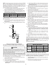
White-Rodgers Model 36G54 Connected to Manometer
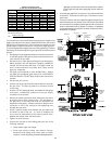
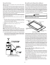
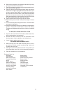
Gas Valve On/Off
Selector Switch
Regulator
Vent
High Fire
Regulator
Adjust
Low Fire
Regulator
Adjust
i
M
a
n
o
m
e
t
e
r
M
a
n
o
m
e
t
e
r
H
o
s
e
Common
Terminal(C)
High Fire Coil
Terminal (HI)
Low Fire Coil
Terminal (LO)
Inlet Pressure Tap
1/8 NPT
O
p
e
n
t
o
A
t
m
o
s
p
h
e
r
e
Outlet Pressure Tap
1/8 NPT
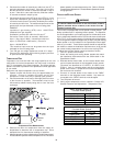
Honeywell Model VR9205 Connected to Manometer
1. Turn OFF gas to furnace at the manual gas shutoff valve
external to the furnace.
2. Connect a calibrated water manometer (or appropriate gas
pressure gauge) at either the gas valve inlet pressure tap
or the gas piping drip leg. See Honeywell VR9205 gas valve
figure or White-Rodgers 36G54 gas valve figure for location
of inlet pressure tap.