


20
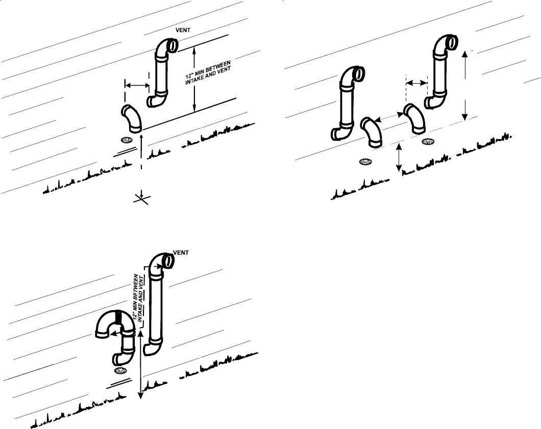
SCREEN
(OPTIONAL)
AIR
INTAKE
90°
ELBOWS
12" MIN. ABOVE
HIGHEST ANTICIPATED
SNOW LEVEL
3” - 24”
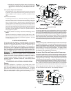
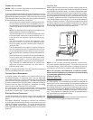
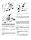
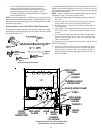
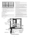
Alternate Horizontal Vent Termination (Dual Pipe)
SCREEN
(OPTIONAL)
AIR
INTAKE
90°
ELBOWS
12" MIN. ABOVE
HIGHEST ANTICIPATED
SNOW LEVEL
3”-24” BETWEEN PIPES
Combustion Air Intake may also be snorkeled to obtain 12” min. ground
clearance.
Alternate Vent Termination Above Anticipated Snow Level
(Dual Pipe)
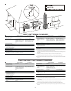
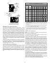
In a basement installation, the pipes may be run between the joist
spaces. If the pipes must go below the joist and then up into the
last joist space to penetrate the header, two 45° elbows should be
used to reach the header rather than two 90° elbows.
VENT/INTAKE T ERMINATIONS F OR I NSTALLATION OF M ULTIPLE
DIRECT V ENT F URNACES
If more than one direct vent furnace is to be installed vertically
through a common roof top, maintain the same minimum clear-
ances between the exhaust vent and air intake terminations of
adjacent units as with the exhaust vent and air intake terminations
of a single unit.
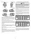
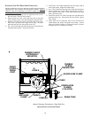
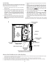
If more than one direct vent furnace is to be installed horizontally
through a common side wall, maintain the clearances as in the
following figure. Always terminate all exhaust vent outlets at the
same elevation and always terminate all air intakes at the same
elevation.
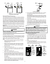
3” MIN
12” MIN TO GRADE OR HIGHEST
ANTICIPATED SNOW LEVEL
12” MIN SEPARATION
3” - 24”
OPTIONAL
INTAKE
SCREENS
Termination of Multiple Direct Vent Furnaces
CONCENTRIC VENT TERMINATION
Refer to the directions provided with the Concentric Vent Kit (DCVK)
for installation specifications.
SIDE WALL VENT KIT
This kit is to be used with 2” or 3” direct vent systems. The vent kit
must terminate outside the structure and may be installed with the
intake and exhaust pipes located side-by-side or with one pipe above
the other. This kit is NOT intended for use with single pipe (indirect
vent) installations.
Refer to the directions furnished with the Side Wall Vent Kit (p/n
0170K00000S) for installation specifications.
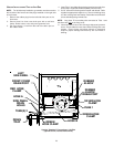
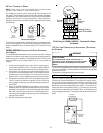
X. CONDENSATE DRAIN LINES & DRAIN TRAP
A condensing gas furnace achieves its high level of efficiency by
extracting almost all of the heat from the products of combustion
and cooling them to the point where condensation takes place.
The condensate which is generated must be piped to an appropri-
ate drain location.
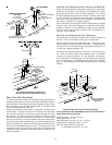
In upright installations, the furnace’s drain hoses may exit either
the right or left side of the furnace. NOTE: If the alternate vent/flue
outlet is utilized in an upright installation, the drain trap and drain
connections must be located on the same side as the alternate
vent/flue outlet.
In horizontal installations, the drain hoses will exit through the
bottom (down side) of the unit with the drain trap suspended be-
neath the furnace. The field-supplied drain system must be in
accordance with all local codes and the instructions in the follow-
ing sections.
Follow the bullets listed below when installing the drain system.
Refer to the following sections for specific details concerning fur-
nace drain trap installation and drain hose hook ups.
• The drain trap supplied with the furnace must be used.
• The drain line between furnace and drain location must
maintain a 1/4 inch per foot downward slope toward
the drain.
• Do not trap the drain line in any other location than at
the drain trap supplied with the furnace.
• If the drain line is routed through an area which may
see temperatures near or below freezing, precautions
must be taken to prevent condensate from freezing
within the drain line.