


30
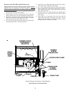
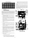
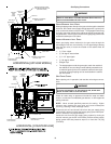
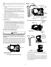
HORIZONTAL [UPFLOW MODEL]
MANUAL SHUT-OFF VALVE
(UPSTREAM FROM GROUND
JOINT PIPE UNION)
DRIP LEG
GROMMET IN STANDARD
GAS LINE HOLE
DRAIN TRAP
ALTERNATE GAS
LINE LOCATION
MANIFOLD
GROMMET IN ALTERNATE
GAS LINE HOLE
GAS VALVE
BURNERS
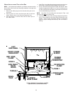
A
LT E RN AT E
UNION
LOCATION
GROUND
JOINT
PIPE
UNION
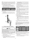
GAS VALVE
BURNERS
MANIFOLD
DRAIN TRAP
ALTERNATE GAS
LINE LOCATION
GORMMET IN ALTERNATE
GAS LINE HOLE
HORIZONTAL [COUNTERFLOW]
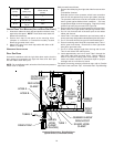
ALTERNATE
UNION
LOCATION
GROUND
JOINT
PIPE
UNION
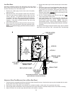
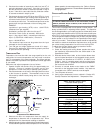
Gas Piping Connections
E
DGES
OF
SHEET
METAL
HOLES
MAY
BE
SHARP
. U
SE
GLOVES
AS
A
PRECAUTION
WHEN
REMOVING
HOLE
PLUGS
.
WARNING
DIRECT/STANDARD INLET PIPING
When gas piping enters directly to the gas valve through the standard
inlet hole, the installer must supply straight pipe with a ground joint
union to reach the exterior of the furnace. The rigid pipe must be long
enough to reach the outside of the cabinet to seal the grommet cabi-
net penetration. A semi-rigid connector to the gas piping can be used
outside the cabinet per local codes.
INDIRECT/ALTERNATE INLET PIPING
When gas piping enters indirectly to the gas valve through the
alternate gas inlet hole, the following 1/2 inch pipe fittings (starting
from the gas valve) to reach the outside of the cabinet must be
supplied:
• (1) Close nipple
• (1) 90 degree street elbow
• (1) 2 1/2” pipe nipple
• (1) 90 degree elbow
• Straight Pipe
• The straight pipe must be long enough to reach the outside of
the cabinet so as to seal the grommet cabinet penetration and
to install the ground joint union outside the cabinet. A semi-rigid
connector to the gas piping can be used outside the cabinet
per local codes.
GAS PIPING CHECKS
Before placing unit in operation, leak test the unit and gas connec-
tions.
T
O
AVOID
THE
POSSIBILITY
OF
EXPLOSION
OR
FIRE
,
NEVER
USE
A
MATCH
OR
OPEN
FLAME
TO
TEST
FOR
LEAKS
.
WARNING
Check for leaks using an approved chloride-free soap and water
solution, an electronic combustible gas detector, or other approved
testing methods.
NOTE: Never exceed specified pressures for testing. Higher
pressure may damage the gas valve and cause subsequent
overfiring, resulting in heat exchanger failure.
Disconnect this unit and shutoff valve from the gas supply piping
system before pressure testing the supply piping system with pres-
sures in excess of 1/2 psig (3.48 kPa).
Isolate this unit from the gas supply piping system by closing its
external manual gas shutoff valve before pressure testing supply
piping system with test pressures equal to or less than 1/2 psig
(3.48 kPa).