


39
PRIMARY LIMIT
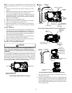
The primary limit control is located on the partition panel and monitors
heat exchanger compartment temperatures. It is a normally-closed
(electrically), automatic reset, temperature-activated sensor. The limit
guards against the overheating as a result of insufficient conditioned
air passing over the heat exchanger.
AUXILIARY LIMIT
The auxiliary limit control(s) are located on or near the circulator blower
and monitors heat exchanger compartment temperatures. They are
a normally-closed (electrically), manual-reset, temperature activated
sensors. These limits guard against overheating as a result of insuf-
ficient conditioned air passing over the heat exchanger.
ROLLOUT LIMIT
The rollout limit control(s) are mounted on the burner/manifold assembly
and monitor the burner flame. They are normally-closed (electrically),
manual-reset, temperature-activated sensors. These limits guard
against burner flames not being properly drawn into the heat exchanger.
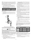
PRESSURE SWITCHES
The pressure switches are normally-open (closed during operation),
single-pole single-throw, negative air pressure-activated switches.
They monitor the airflow (combustion air and flue products) through
the heat exchanger via pressure taps located on the induced draft
blower and the coil front cover. These switches guard against insuffi-
cient airflow (combustion air and flue products) through the heat ex-
changer and/or blocked condensate drain conditions.
FLAME SENSOR
The flame sensor is a probe mounted to the burner/manifold assem-
bly which uses the principle of flame rectification to determine the pres-
ence or absence of flame.
XVIII. TROUBLESHOOTING
ELECTROSTATIC DISCHARGE (ESD) PRECAUTIONS
NOTE: Discharge body’s static electricity before touching unit. An
electrostatic discharge can adversely affect electrical components.
Use the following precautions during furnace installation and ser-
vicing to protect the integrated control module from damage. By
putting the furnace, the control, and the person at the same electro-
static potential, these steps will help avoid exposing the integrated
control module to electrostatic discharge. This procedure is appli-
cable to both installed and uninstalled (ungrounded) furnaces.
1. Disconnect all power to the furnace. Do not touch the
integrated control module or any wire connected to the control
prior to discharging your body’s electrostatic charge to ground.
2. Firmly touch a clean, unpainted, metal surface of the furnaces
near the control. Any tools held in a person’s hand during
grounding will be discharged.
3. Service integrated control module or connecting wiring following
the discharge process in step 2. Use caution not to recharge
your body with static electricity; (i.e., do not move or shuffle
your feet, do not touch ungrounded objects, etc.). If you come
in contact with an ungrounded object, repeat step 2 before
touching control or wires.
4. Discharge your body to ground before removing a new control
from its container. Follow steps 1 through 3 if installing the
control on a furnace. Return any old or new controls to their
containers before touching any ungrounded object.
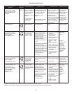
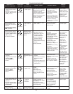
DIAGNOSTIC CHART
HIGH VOLTAGE!
T
O
AVOID
PERSONAL
INJURY
OR
DEATH
DUE
TO
ELECTRICAL
SHOCK
,
DISCONNECT
ELECTRICAL
POWER
BEFORE
P
ERFORMAING
ANY
SERVICE
OR
MAINTENANCE
.
WARNING
Refer to the Troubleshooting Chart at the end of this manual for assis-
tance in determining the source of unit operational problems. The red
diagnostic LED blinks to assist in troubleshooting the unit. The num-
ber of blinks refers to a specific fault code.
FAULT RECALL
The ignition control is equipped with a momentary pushbutton switch
that can be used to display on the diagnostic LED the last five faults
detected by the control. The control must be in Standby Mode (no ther-
mostat inputs) to use the feature. Depress the pushbutton switch for
approximately 2 seconds. Release the switch when the LED is turned
off. The diagnostic LED will then display the flash codes associated
with the last five detected faults. The order of display is the most re-
cent fault to the least recent fault.
RESETTING FROM LOCKOUT
Furnace lockout results when a furnace is unable to achieve ignition
after three attempts during a single call for heat. It is characterized by
a non-functioning furnace and a one flash diagnostic LED code. If the
furnace is in “lockout”, it will (or can be) reset in any of the following
ways.
1. Automatic reset. The integrated control module will
automatically reset itself and attempt to resume normal
operations following a one hour lockout period.
2. Manual power interruption. Interrupt 115 volt power to the
furnace for 1 - 20 seconds.
3. Manual thermostat cycle. Lower the thermostat so that
there is no longer a call for heat then reset to previous setting.
Interrupt thermostat signal to the furnace for 1 - 20 seconds.
NOTE: If the condition which originally caused the lockout still
exists, the control will return to lockout. Refer to Troubleshooting -
Diagnostic Chart for aid in determining the cause.