


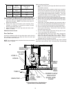

28
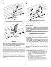
If it is necessary for the installer to supply additional line voltage wiring
to the inside of the furnace, the wiring must conform to all local codes,
and have a minimum temperature rating of 105°C. All line voltage wire
splices must be made inside the furnace junction box.
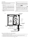
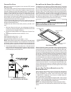
The integrated control module electronic air cleaner terminals (EAC)
are energized with 115 volts whenever the circulator blower is en-
ergized.
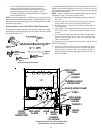
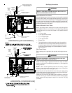
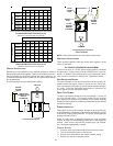
24 VOLT HUMIDIFIER
The yellow wire connected to the I.D. Blower pressure switch is
powered anytime the pressure switch is closed and provides 24
VAC humidifier control. Remove the yellow wire and connect a field
supplied jumper wire with a “piggyback” terminal to the pressure
switch terminal. Reconnect the yellow wire to the “piggyback” ter-
minal on the jumper wire and then connect the 24 VAC line of the
humidifier to the stripped end of the jumper wire. Using a wire nut
or a field-supplied quick connect terminal can make this connec-
tion. The wiring must conform to all local and national codes. Con-
nect the COM side of the humidifier to the B/C terminal on the
furnace control board (or to the COM side of the 24 VAC trans-
former). DO NOT CONNECT 115V HUMIDIFIER TO THESE TERMI-
NALS.
XII. GAS SUPPLY AND PIPING
GENERAL
The furnace rating plate includes the approved furnace gas input
rating and gas types. The furnace must be equipped to operate on
the type of gas applied. This includes any conversion kits required
for alternate fuels and/or high altitude.
T
O
PREVENT
UNRELIABLE
OPERATION
OR
EQUIPMENT
DAMAGE
,
THE
I
NLET
GAS
SUPPLY
PRESSURE
MUST
BE
AS
SPECIFIED
ON
THE
UNIT
RATING
PLATE
WITH
ALL
OTHER
HOUSEHOLD
GAS
FIRED
APPLIANCES
OPERATING
.
CAUTION
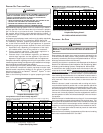
Inlet gas supply pressures must be maintained within the ranges
specified below. The supply pressure must be constant and avail-
able with all other household gas fired appliances operating. The
minimum gas supply pressure must be maintained to prevent
unreliable ignition. The maximum must not be exceeded to pre-
vent unit overfiring.
Natural Gas Minimum: 4.5" w.c. Maximum: 10.0" w.c.
Propane Gas Minimum: 11.0" w.c. Maximum: 13.0" w.c.
Inlet Gas Supply Pressure
HIGH ALTITUDE DERATE
When this furnace is installed at high altitude, the appropriate High
Altitude orifice kit must be applied. This is required due to the
natural reduction in the density of both the gas fuel and combus-
tion air as altitude increases. The kit will provide the proper design
certified input rate within the specified altitude range.
High altitude kits are purchased according to the installation alti-
tude and usage of either natural or propane gas. Contact your
distributor for a tabular listing of appropriate altitude ranges and
corresponding manufacturer’s high altitude (Natural, Propane Gas,
and/or Pressure Switch) kits.
Do not derate the furnace by adjusting the manifold pressure to a
lower pressure than specified on the furnace rating plate. The
combination of the lower air density and a lower manifold pressure
will prohibit the burner orifice from drawing the proper amount of
air into the burner. This may cause incomplete combustion, flash-
back, and possible yellow tipping.
In some areas the gas supplier may artificially derate the gas in an
effort to compensate for the effects of altitude. If the gas is artificially
derated, the appropriate orifice size must be determined based upon
the BTU/ft
3
content of the derated gas and the altitude. Refer to the
National Fuel Gas Code, NFPA 54/ANSI Z223.1, and information pro-
vided by the gas supplier to determine the proper orifice size.
A different pressure switch may be required at high altitude regardless
of the BTU/ft
3
content of the fuel used. Contact your distributor for a
tabular listing of appropriate altitude ranges and corresponding
manufacturer’s pressure switch kits.
PROPANE GAS CONVERSION
P
OSSIBLE
PROPERTY
DAMAGE
,
PERSONAL
INJURY
OR
DEATH
MAY
OCCUR
IF
THE
CORRECT
CONVERSION
KITS
ARE
NOT
INSTALLED
. T
HE
APPROPRIATE
KITS
MUST
BE
APPLIED
TO
ENSURE
SAFE
AND
PROPER
FURNACE
OPERATION
. A
LL
CONVERSIONS
MUST
BE
PERFORMED
BY
A
QUALIFIED
INSTALLER
OR
SERVICE
AGENCY
.
WARNING
This unit is configured for natural gas. The appropriate
manufacturer’s propane gas conversion kit, must be applied for
propane gas installations. Refer to the Section VIII, Propane Gas
/ High Altitude Installations section for details.
Consult the furnace Specification Sheet for a listing of appropirate
kits. The indicated kits must be used to insure safe and proper
furnace operation. All conversions must be performed by a quali-
fied installer or service agency.
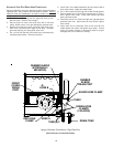
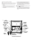
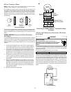
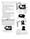
GAS VALVE
This unit is equipped with a 24 volt gas valve controlled during
furnace operation by the integrated control module. As shipped,
the valve is configured for natural gas. The valve is field convertible
for use with propane gas by replacing the regulator spring with a
propane gas spring from an appropriate manufacturer’s propane
gas conversion kit. Taps for measuring the gas supply pressure
and manifold pressure are provided on the valve.
The gas valve has a manual ON/OFF control located on the valve
itself. This control may be set only to the “ON” or “OFF” position.
Refer to the lighting instructions label or Section XIV, Startup Pro-
cedure & Adjustment for use of this control during start up and shut
down periods.
GAS PIPING CONNECTIONS
GENERAL
CAUTION
T
O AVOID POSSIBLE UNSATISFACTORY OPERATION OR EQUIPMENT DAMAGE
DUE TO UNDERFIRING OF EQUIPMENT, USE THE PROPER SIZE OF
NATURAL/PROPANE GAS PIPING NEEDED WHEN RUNNING PIPE FROM THE
METER/TANK TO THE FURNACE.
When sizing a trunk line, be sure to include all appliances which
will operate simultaneously.
The gas piping supplying the furnace must be properly sized based
on the gas flow required, specific gravity of the gas, and length of
the run. The gas line installation must comply with local codes, or
in their absence, with the latest edition of the National Fuel Gas
Code, NFPA 54/ANSI Z223.1.