


Application – All Motors
WARNING: To prevent accidental electrocution,
automatic or manual transfer switches must be used
any time a generator is used as standby or back
up on power lines. Contact power company for use
and approval.
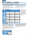
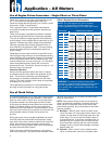
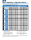
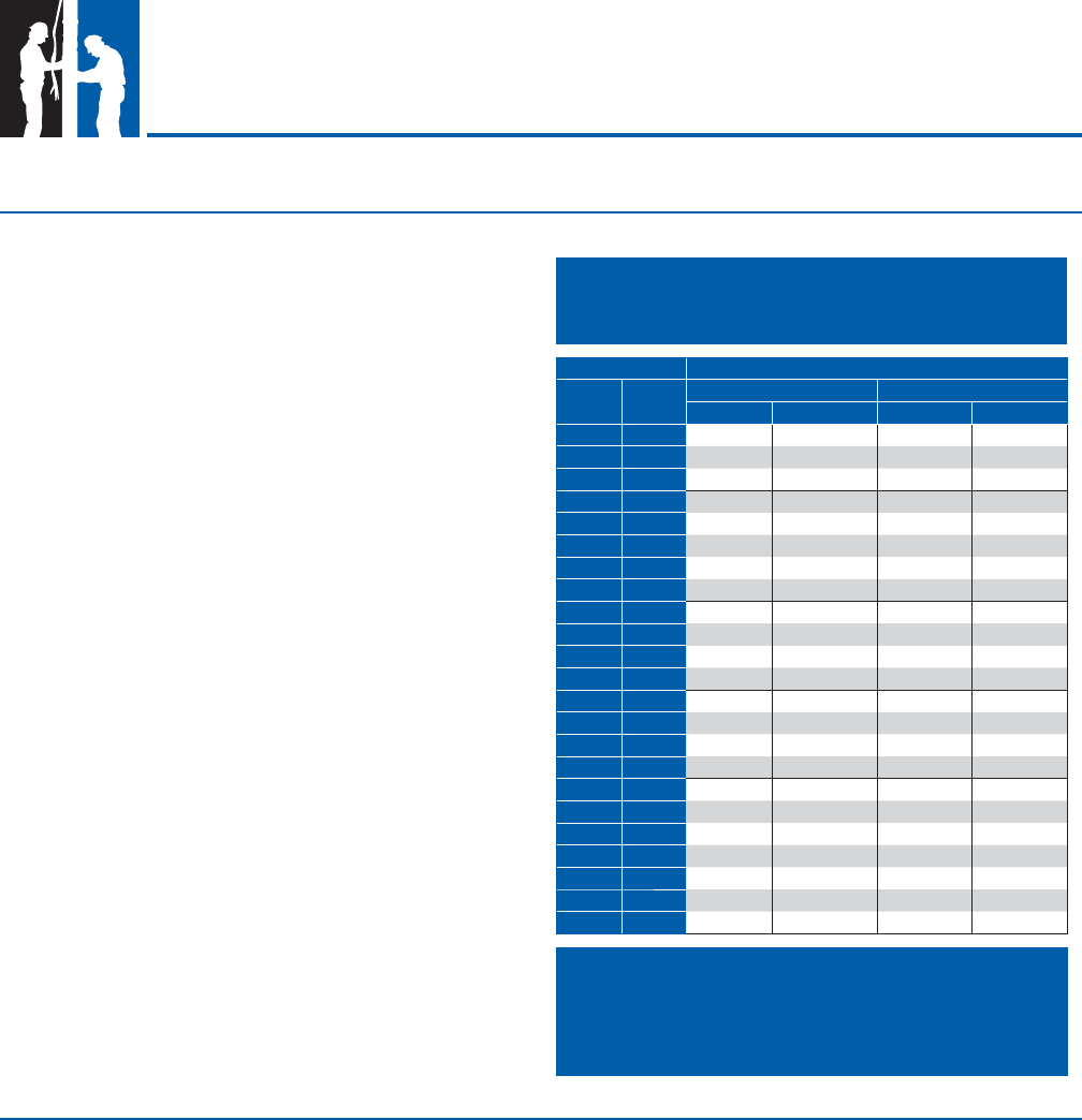
Table 5 lists minimum generator sizes based on typical
80 °C rise continuous duty generators, with 35%
maximum voltage dip during starting, for Franklin’s three-
wire motors, single- or three-phase.
This is a general chart. The generator manufacturer
should be consulted whenever possible, especially on
larger sizes.
There are two types of generators available: externally
and internally regulated. Most are externally regulated.
They use an external voltage regulator that senses the
output voltage. As the voltage dips at motor start-up, the
regulator increases the output voltage of the generator.
Internally regulated (self-excited) generators have an
extra winding in the generator stator. The extra winding
senses the output current to automatically adjust the
output voltage.
Generators must be sized to deliver at least 65% of the
rated voltage during starting to ensure adequate starting
torque. Besides sizing, generator frequency is important
as the motor speed varies with the frequency (Hz). Due
to pump affi nity laws, a pump running at 1 to 2 Hz below
motor nameplate frequency design will not meet its
performance curve. Conversely, a pump running at 1 to 2
Hz above may trip overloads.
Generator Operation
Always start the generator before the motor is started
and always stop the motor before the generator is shut
down. The motor thrust bearing may be damaged if
the generator is allowed to coast down with the motor
running. This same condition occurs when the generator
is allowed to run out of fuel.
Follow generator manufacturer’s recommendations for
de-rating at higher elevations or using natural gas.
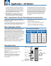
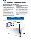
It is recommended that one or more check valves always
be used in submersible pump installations. If the pump
does not have a built-in check valve, a line check valve
should be installed in the discharge line within 25 feet
of the pump and below the draw down level of the water
supply. For deeper settings, check valves should be
installed per the manufacturer’s recommendations. More
than one check valve may be required, but more than the
recommended number of check valves should not
be used.
Swing type check valves are not acceptable and should
never be used with submersible motors/pumps. Swing
type check valves have a slower reaction time which can
cause water hammer (see next page). Internal pump
check valves or spring loaded check valves close quickly
and help eliminate water hammer.
Check valves are used to hold pressure in the system
when the pump stops. They also prevent backspin, water
hammer and upthrust. Any of these can lead to early
pump or motor failure.
NOTE: Only positive sealing check valves should be
used in submersible installations. Although drilling the
check valves or using drain-back check valves may
prevent back spinning, they create upthrust and water
hammer problems.
A. Backspin - With no check valve or a failed check
valve, the water in the drop pipe and the water in the
system can fl ow down the discharge pipe when the
motor stops. This can cause the pump to rotate in
a reverse direction. If the motor is started while it is
backspinning, an excessive force is placed across
the pump-motor assembly that can cause impeller
damage, motor or pump shaft breakage, excessive
bearing wear, etc.
B. Upthrust - With no check valve, a leaking check
valve, or drilled check valve, the unit starts under
Use of Engine Driven Generators - Single-Phase or Three-Phase
Table 5 Engine Driven Generators
MOTOR RATING MINIMUM RATING OF GENERATOR
HP KW
EXTERNALLY REGULATED INTERNALLY REGULATED
KW KVA KW KVA
1/3 0.25
1.5 1.9 1.2 1.5
1/2 0.37
2 2.5 1.5 1.9
3/4 0.55
3 3.8 2 2.5
1 0.75
4 5.0 2.5 3.13
1.5 1.1
5 6.25 3 3.8
2 1.5
7.5 9.4 4 5
3 2.2
10 12.5 5 6.25
5 3.7
15 18.75 7.5 9.4
7.5 5.5
20 25.0 10 12.5
10 7.5
30 37.5 15 18.75
15 11
40 50 20 25
20 15
60 75 25 31
25 18.5
75 94 30 37.50
30 22
100 125 40 50
40 30
100 125 50 62.5
50 37
150 188 60 75
60 45
175 220 75 94
75 55
250 313 100 125
100 75
300 375 150 188
125 90
375 469 175 219
150 110
450 563 200 250
175 130
525 656 250 313
200 150
600 750 275 344
Use of Check Valves
NOTE: This chart applies to 3-wire or 3-phase
motors. For best starting of 2-wire motors, the
minimum generator rating is 50% higher than shown.
5