


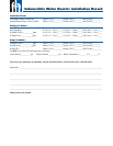
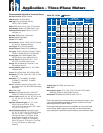
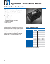

Application – Three-Phase Motors
1
50
= 0.02 or 2%
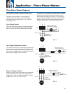
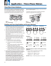
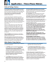
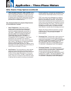
A full three-phase supply is recommended for all three-
phase motors, consisting of three individual transformers
or one three-phase transformer. So-called “open” delta
or wye connections using only two transformers can be
used, but are more likely to cause problems, such as
poor performance, overload tripping or early motor failure
due to current unbalance.
Transformer rating should be no smaller than listed in
table 4 for supply power to the motor alone.
1. Established correct motor rotation by running in both
directions. Change rotation by exchanging any two
of the three motor leads. The rotation that gives the
most water fl ow is always the correct rotation.
2. After correct rotation has been established, check the
current in each of the three motor leads and calculate
the current unbalance as explained in 3 below.
If the current unbalance is 2% or less, leave the leads
as connected.
If the current unbalance is more than 2%, current
readings should be checked on each leg using each
of three possible hook-ups. Roll the motor leads
across the starter in the same direction to prevent
motor reversal.
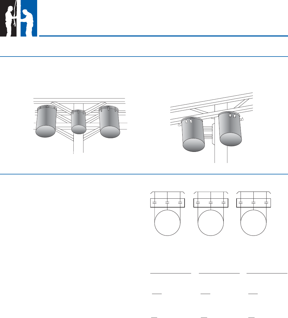
3. To calculate percent of current unbalance:
A. Add the three line amps values together.
B. Divide the sum by three, yielding average
current.
C. Pick the amp value which is furthest from the
average current (either high or low).
D. Determine the difference between this amp
value (furthest from average) and the average.
E. Divide the difference by the average. Multiply the
result by 100 to determine percent of unbalance.
4. Current unbalance should not exceed 5% at service
factor load or 10% at rated input load. If the unbalance
cannot be corrected by rolling leads, the source of
the unbalance must be located and corrected. If,
on the three possible hookups, the leg farthest from
the average stays on the same power lead, most
of the unbalance is coming from the power source.
However, if the reading farthest from average moves
with the same motor lead, the primary source of
unbalance is on the “motor side” of the starter. In this
instance, consider a damaged cable, leaking splice,
poor connection, or faulty motor winding.
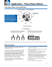
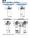
Checking and Correcting Rotation and Current Unbalance
T2
T1
T3
L1
L2
L3
T1
T3
T2
L1
L2
L3
T3
T2
T1
L1
L2
L3
1st Hook Up 2nd Hook Up 3rd Hook Up
supply
starter
motor
EXAMPLE:
T1 = 51 amps T3 = 50 amps T2 = 50 amps
T2 = 46 amps T1 = 49 amps T3 = 48 amps
T3 = 53 amps T2 = 51 amps T1 = 52 amps
Total = 150 amps Total = 150 amps Total = 150 amps
+
+
+
50 - 46 = 4 amps 50 - 49 = 1 amp 50 - 48 = 2 amps
2
50
= 0.04 or 4%
Phase designation of leads for CCW rotation viewing
shaft end.
To reverse rotation, interchange any two leads.
Phase 1 or “A” - Black, T1, or U1
Phase 2 or “B” - Yellow, T2, or V1
Phase 3 or “C” - Red, T3, or W1
NOTICE: Phase 1, 2 and 3 may not be L1, L2 and L3.
FIG. 10
FULL THREE-PHASE
FIG. 11
OPEN DELTA
150
3
= 50 amps
150
3
= 50
amps
4
50
= 0.08 or 8%
150
3
= 50 amps
Three-Phase Power Unbalance
33