


Application – Three-Phase Motors
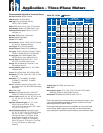
Three-Phase Motor Lead Identifi cation
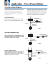
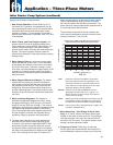
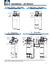
Each motor lead is numbered with two markers, one near each end. To reverse rotation, interchange any two line connections.
L1
T1
U1
T1
U1
T6
W2
T6
W2
L2
T2
V1
T2
V1
T4
U2
T4
U2
L3
T3
W1
T3
W1
T5
V2
T5
V2
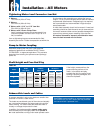
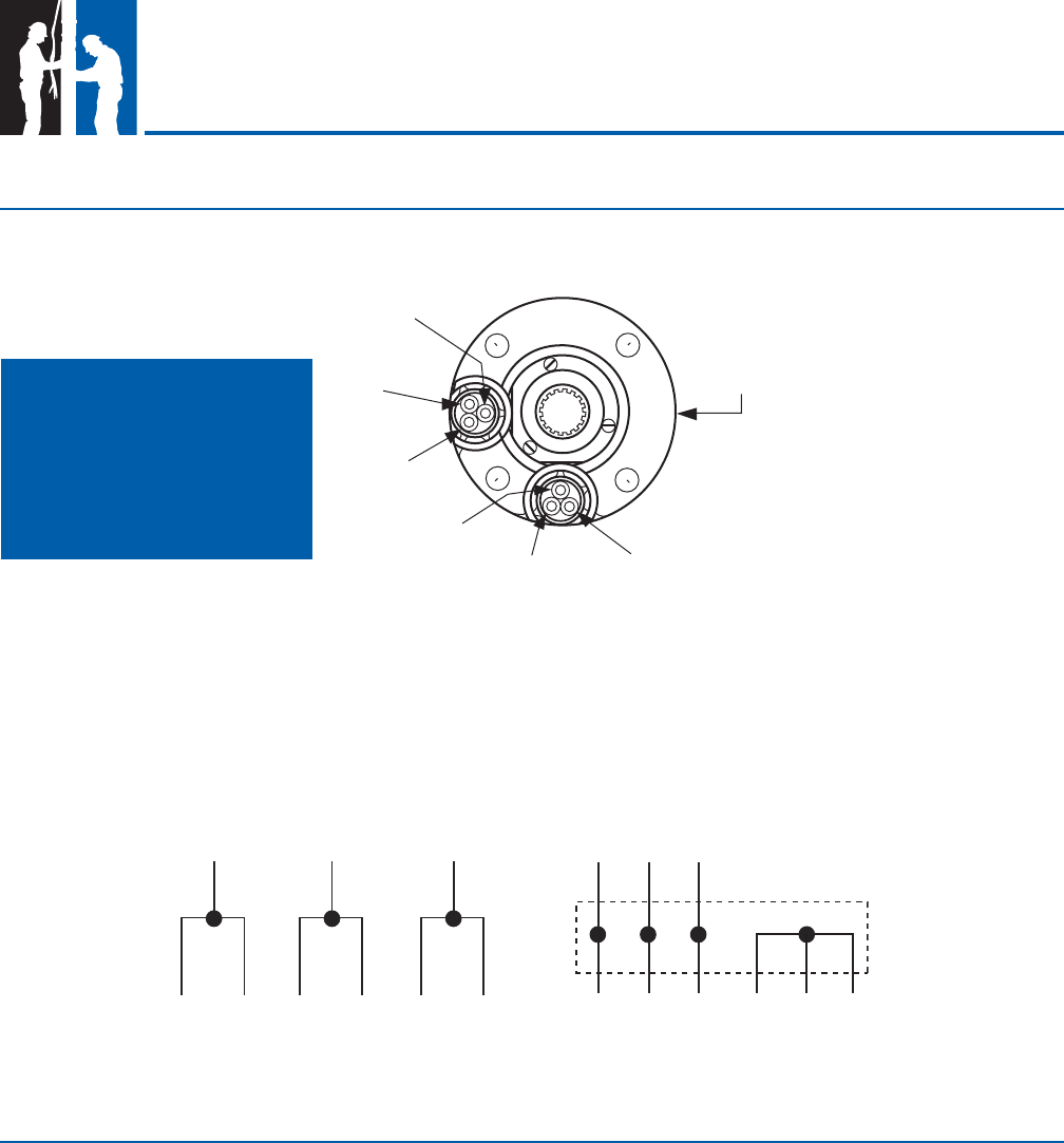
L1 L2 L3
Connections for across-the-line starting,
running, and any reduced voltage starting
except WYE-DELTA type starters.
WYE-DELTA starters connect the motor as
shown below during starting, then change to
the running connection shown at the left.
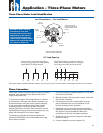
There are a number of different types of phase converters
available. Each generates three-phase power from a
single-phase power line.
In all phase converters, the voltage balance is critical to
current balance. Although some phase converters may
be well balanced at one point on the system-operating
curve, submersible pumping systems often operate
at differing points on the curve as water levels and
operating pressures fl uctuate. Other converters may be
well balanced at varying loads, but their output may vary
widely with fl uctuations in the input voltage.
The following guidelines have been established for
submersible installations to be warrantable when used
with a phase converter.
1. Limit pump loading to rated horsepower. Do not load
into motor service factor.
2. Maintain at least 3 ft/s fl ow past the motor. Use a fl ow
sleeve when necessary.
3. Use time delay fuses or circuit breakers in pump
panel. Standard fuses or circuit breakers do not
provide secondary motor protection.
4. SubMonitor may be used with electro mechanical
type phase converters, however special connections
are required. Consult SubMonitor Manual for
connections of receiver and lightning arrestor.
5. SubMonitor will not work with electronic solid state
phase converters.
6. Current unbalance must not exceed 10%.
T5-V2
(YELLOW)
T2-V1
(YELLOW)
T4-U2
(BLACK)
T1-U1
(BLACK)
T6-W2
(RED)
T3-W1
(RED)
LEADS LOCATED HERE ONLY
FOR 3 LEAD
(
DOL
)
MOTORS
CHECK VALVE OR
PIPE PLUG ON RIGHT
SIDE FACING MOTOR
SHAFT
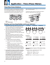
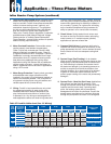
WARNING: When installing
6-lead motors extra care
must be used to ensure lead
identifi cation at the surface.
Leads must be marked and
connected per diagram. Motor
leads are not connected red to
red, yellow to yellow, etc.
Line Connections — Six-Lead Motors
90° Lead Spacing
Phase Converters
34