


Maintenance – Single-Phase Motors & Controls
WARNING: Power must be on for these tests. Do not
touch any live parts.
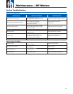
A. VOLTAGE MEASUREMENTS
Step 1. Motor Off
1. Measure voltage at L1 and L2 of pressure switch
or line contactor.
2. Voltage Reading: Should be ± 10% of
motor rating.
Step 2. Motor Running
1. Measure voltage at load side of pressure switch
or line contactor with pump running.
2. Voltage Reading: Should remain the same except
for slight dip on starting. Excessive voltage
drop can be caused by loose connections, bad
contacts, ground faults, or inadequate
power supply.
3. Relay chatter is caused by low voltage or
ground faults.
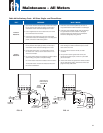
If the colors on the individual drop cables cannot be
found with an Ohmmeter, measure:
Cable 1 to Cable 2
Cable 2 to Cable 3
Cable 3 to Cable 1
Find the highest resistance reading.
The lead not used in the highest reading is the
yellow lead.
Use the yellow lead and each of the other two leads to
get two readings:
Highest is the red lead.
Lowest is the black lead.
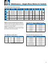
Identifi cation Of Cables When Color Code Is Unknown (Single-Phase 3-Wire Units)
EXAMPLE:
The Ohmmeter readings were:
Cable 1 to Cable 2—6 ohms
Cable 2 to Cable 3—2 ohms
Cable 3 to Cable 1— 4 ohms
The lead not used in the highest reading (6 ohms) was
Cable 3—Yellow
From the yellow lead, the highest reading (4 ohms) was
To Cable 1—Red
From the yellow lead, the lowest reading (2 ohms) was
To Cable 2—Black
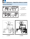
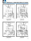
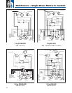
Single-Phase Control Boxes
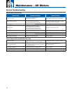
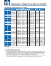
B. CURRENT (AMP) MEASUREMENTS
1. Measure current on all motor leads.
2. Amp Reading: Current in red lead should
momentarily be high, then drop within one second
to values in table 13. This verifi es relay or solid
state relay operation. Current in black and yellow
leads should not exceed values in table 13.
3. Relay or switch failures will cause red lead
current to remain high and overload tripping.
4. Open run capacitor(s) will cause amps to be
higher than normal in the black and yellow motor
leads and lower than normal in the red
motor lead.
5. A bound pump will cause locked rotor amps and
overloading tripping.
6. Low amps may be caused by pump running at
shutoff, worn pump, or stripped splines.
7. Failed start capacitor or open switch/relay are
indicated if the red lead current is not
momentarily high at starting.
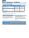
CAUTION: The tests in this manual for components such as capacitors, relays, and QD switches should be
regarded as indicative and not as conclusive. For example, a capacitor may test good (not open, not shorted) but
may have lost some of its capacitance and may no longer be able to perform its function.
To verify proper operation of QD switches or relays, refer to operational test procedure described above
in Section B-2.
Checking and Repairing Procedures (Power On)
46