


Application – Three-Phase Motors
O.L. CONTACTS
PRESSURE SWITCH OR
OTHER CONTROL DEVICE
COIL
L1
L2
L3
FUSES
CONTACTS
OVERLOAD
HEATERS AND/OR
MOTOR
SUBTROL PLUS
O.L. CONTACTS
PRESSURE SWITCH OR
OTHER CONTROL DEVICE
L1
L2
L3
FUSES
CONTACTS
OVERLOAD
HEATERS AND/OR
MOTOR
TRANSFORMER
COIL
FUSE
SUBTROL PLUS
O.L. CONTACTS
PRESSURE SWITCH OR
OTHER CONTROL DEVICE
L1
L2
L3
FUSES
CONTACTS
OVERLOAD
HEATER AND/OR
MOTOR
COIL
TO SEPARATE
CONTROL VOLTAGE
SOURCE
SUBTROL DEVICE
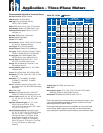
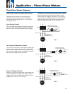
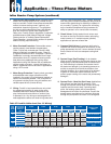
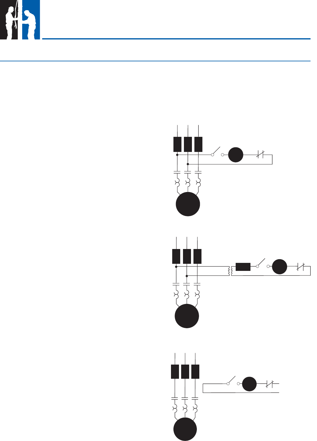
Three-phase combination magnetic starters have two
distinct circuits: a power circuit and a control circuit.
The power circuit consists of a circuit breaker or
fused line switch, contacts, and overload heaters
connecting incoming power lines L1, L2, L3 and the
three-phase motor.
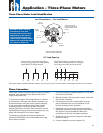
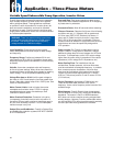
External Voltage Controls
Control of a power circuit by a lower circuit voltage can
also be obtained by connecting to a separate control
voltage source. The coil rating must match the control
voltage source, such as 115 or 24 volts.
The control circuit consists of the magnetic coil, overload
contacts and a control device such as a pressure switch.
When the control device contacts are closed, current
fl ows through the magnetic contactor coil, the contacts
close, and power is applied to the motor. Hand-Off-Auto
switches, start timers, level controls and other control
devices may also be in series in the control circuit.
Line Voltage Control
This is the most common type of control encountered.
Since the coil is connected directly across the power
lines L1 and L2, the coil must match the line voltage.
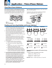
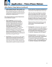
Low Voltage Transformer Control
This control is used when it is desirable to operate push
buttons or other control devices at some voltage lower
than the motor voltage. The transformer primary must
match the line voltage and the coil voltage must match
the secondary voltage of the transformer.
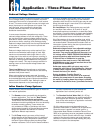
FIG. 7
FIG. 8
FIG. 9
Three-Phase Starter Diagrams
32