Maintenance – Single-Phase Motors & Controls
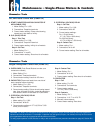
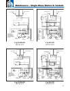
Integral Horsepower Control Box (Power Off)
A. OVERLOADS (Push Reset Buttons to make sure
contacts are closed.)
1. Meter Setting: R x 1.
2. Connections: Overload terminals.
3. Correct meter reading: Less than 0.5 ohms.
B. CAPACITOR (Disconnect leads from one side of
each capacitor before checking.)
1. Meter Setting: R x 1,000.
2. Connections: Capacitor terminals.
3. Correct meter reading: Pointer should swing toward
zero, then drift back to infi nity, except for capacitors
with resistors which will drift back to 15,000 ohms.
C. POTENTIAL (VOLTAGE) RELAY
Step 1. Coil Test
1. Meter setting: R x 1,000.
2. Connections: #2 & #5.
3. Correct meter readings: 4.5-7.0 (4,500 to 7,000
ohms) for all models.
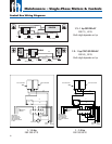
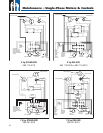
QD, Solid State Control Box (Power Off)
A. START CAPACITOR AND RUN CAPACITOR IF
APPLICABLE (CRC)
1. Meter Setting: R x 1,000.
2. Connections: Capacitor terminals.
3. Correct meter reading: Pointer should swing
toward zero, then back to infi nity.
B. Q.D. (BLUE) RELAY
Step 1. Triac Test
1. Meter setting: R x 1,000.
2. Connections: Cap and B terminal.
3. Correct meter reading: Infi nity for all models.
Step 2. Coil Test
1. Meter Setting: R x 1.
2. Connections: L1 and B.
3. Correct meter reading: Zero ohms for all models.
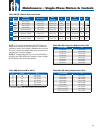
CAUTION: The tests in this manual for components such as capacitors, relays, and QD switches should be regarded as
indicative and not as conclusive. For example, a capacitor may test good (not open, not shorted) but may have lost some
of its capacitance and may no longer be able to perform its function.
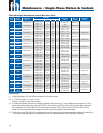
To verify proper operation of QD switches or relays, refer to operational test procedure described on page 46, Section B-2.
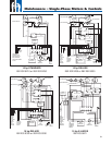
C. POTENTIAL (VOLTAGE) RELAY
Step 1. Coil Test
1. Meter setting: R x 1,000.
2. Connections: #2 & #5.
3. Correct meter readings:
For 115 Volt Boxes:
0.7-1.8 (700 to 1,800 ohms).
For 230 Volt Boxes:
4.5-7.0 (4,500 to 7,000 ohms).
Step 2. Contact Test
1. Meter setting: R x 1.
2. Connections: #1 & #2.
3. Correct meter reading: Zero for all models.
Step 2. Contact Test
1. Meter Setting: R x 1.
2. Connections: #1 & #2.
3. Correct meter reading: Zero ohms for all models.
D. CONTACTOR
Step 1. Coil
1. Meter setting: R x 100
2. Connections: Coil terminals
3. Correct meter reading:
1.8-14.0 (180 to 1,400 ohms)
Step 2. Contacts
1. Meter Setting: R X 1
2. Connections: L1 & T1 or L2 & T2
3. Manually close contacts
4. Correct meter reading: Zero ohms
Ohmmeter Tests
Ohmmeter Tests
47


