


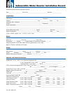
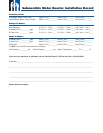

1. Motor Inspection
A. Verify that the model, hp or kW, voltage, phase and hertz on the motor nameplate match the
installation requirements.
B. Check that the motor lead assembly is not damaged.
C. Measure insulation resistance using a 500 or 1000 volt DC megohmmeter from each lead wire to the
motor frame. Resistance should be at least 200 megohms without drop cable.
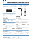
D. Keep a record of motor model number, hp or kW, voltage, and serial number (S/N).
(S/N is stamped in shell above the nameplate. A typical example, S/N 07A18 01-0123)
2. Pump Inspection
A. Check that the pump rating matches the motor.
B. Check for pump damage and verify that the pump shaft turns freely.
3. Pump/Motor Assembly
A. If not yet assembled, check that pump and motor mounting faces are free from dirt, debris and uneven
paint thickness.
B. Pumps and motors over 5 hp should be assembled in the vertical position to prevent stress on pump
brackets and shafts. Assemble the pump and motor together so their mounting faces are in contact and
then tighten assembly bolts or nuts evenly to manufacturer specifi cations.
C. If accessible, check that the pump shaft turns freely.
D. Assemble the pump lead guard over the motor leads. Do not cut or pinch lead wires during assembly or
installation.
4. Power Supply and Controls
A. Verify that the power supply voltage, hertz, and kVA capacity match motor requirements.
B. Verify control box hp and voltage matches motor (3-wire only).
C. Check that the electrical installation and controls meet all safety regulations and match the motor
requirements, including fuse or circuit breaker size and motor overload protection. Connect all metal
plumbing and electrical enclosures to the power supply ground to prevent shock hazard. Comply with
national and local codes.
5. Lightning and Surge Protection
A. Use properly rated surge (lightning) arrestors on all submersible pump installations. Motors 5 hp and
smaller, which are marked “Equipped with Lightning Arrestors”, contain internal arrestors.
B. Ground all above ground arrestors with copper wire directly to the motor frame, or to metal drop pipe or
casing which reaches below the well pumping level. Connecting to a ground rod does not provide good
surge protection.
6. Electrical Drop Cable
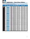
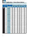
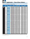
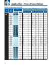
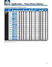
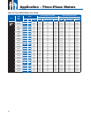
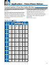
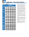
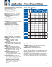
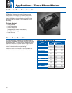
A. Use submersible cable sized in accordance with local regulations and the cable charts, see pages 11 and 16-21.
Ground motor per national and local codes.
B. Include a ground wire to the motor and surge protection, connected to the power supply ground if
required by codes. Always ground any pump operated outside a drilled well.
7. Motor Cooling
A. Ensure at all times that the installation provides adequate motor cooling; see page 6 for details.
8. Pump/Motor Installation
A. Splice motor leads to supply cable using electrical grade solder or compression connectors, and carefully
insulate each splice with watertight tape or adhesive-lined shrink tubing, as shown in motor or pump
installation data.
B. Support the cable to the delivery pipe every 10 feet (3 meters) with straps or tape strong enough to
prevent sagging. Use padding between cable and any metal straps.
C. A check valve in the delivery pipe is recommended. More than one check valve may be required,
depending on valve rating and pump setting; see page 5 for details.
D. Assemble all pipe joints as tightly as practical, to prevent unscrewing from motor torque. Torque should
be at least 10 pound feet per hp (2 meter-KG per kW).
E. Set the pump far enough below the lowest pumping level to assure the pump inlet will always have at
least the Net Positive Suction Head (NPSH) specifi ed by the pump manufacturer. Pump should be at
least 10 feet (3 meters) from the bottom of the well to allow for sediment build up.
❑
❑
❑
❑
❑
❑
❑
❑
❑
❑
❑
❑
❑
❑
❑
❑
❑
❑
❑
❑
❑
❑
❑
Form No. 3656 02/07
Submersible Pump Installation Check List